Continue to Site

Welcome to EDAboard.com

Welcome to our site! EDAboard.com is an international Electronics Discussion Forum focused on EDA software, circuits, schematics, books, theory, papers, asic, pld, 8051, DSP, Network, RF, Analog Design, PCB, Service Manuals... and a whole lot more! To participate you need to register. Registration is free. Click here to register now.

[SOLVED] 1-Turn inductor (transformer's primary)

Status
Not open for further replies.
R

red_alert

Guest
Hello,

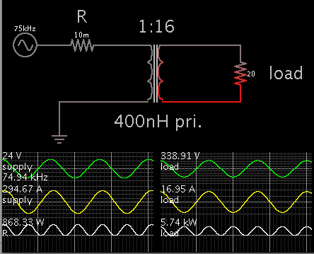
I need to design a ferrite transformer for a 4kW DC-DC full bridge converter (24V -> 350V). I'm going to use ETD59 (if it could handle 4kW) or E71 ferrite core (3C90), working at 75-100kHz.

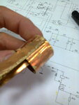
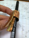
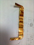
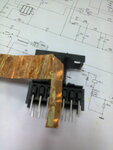
After many calculations, using some software tools or designing formulas, seems like the primary inductor should have 1 (one) turn of very thick (litz) wire.

How to practically make it? I think I'll have to "spread" it across the entire ferrite core.. or should I have one single (thick) wire in the middle?

Do you know a feasible way to do this? How to better interleave the primary and secondary inductors?

Thanks in advance for any support.
 

4 KW @ 24V = 170A !! I would have thought that you would need something at least a 10mm cross section conductor. Trying to spread the one turn of wire around a core, will lead to a greater length of wire and the mechanical problem of holding the wire in the right place ( loads of small cable ties?, glue?). The wire should be taken right to the power devices all in litz. If you are using parallel output devices, reconfigure them and the primary so you can split the 170As into two or more windings which go to their own output devices. You will need sufficient 24V decoupling capacitors to handle that amount of ripple.
Frank
 

May I use multiple 1-turn coils for primary inductor (made of commercially available 3-4mm2 litz wire) parallel connected?

For example, to have 10 primary coils (1 turn each) spreaded along the core.

Or it's a better solution to use a single (diy) thick litz wire spreaded diagonally along the core, with single input/ouput?


PS: Unfortunatelly, I can't split the load - it's a big electric oven. Is there a way to put multiple HF transformers in parallel (I'm using a full bridge DC-DC converter)? May I use parallel conection for primary coils and serial connection for secondary coils?
 
Last edited:

For those instances, one must use copper foil instead. This is a very common practice and used it myself.
 

A foil winding isn't bad, but it might not suffice for the present transformer configuration. The complete high AC current path must be designed aware of skin and proximity effect. Splitting the primary circuit into multiple parallel current pathes, as suggested, is probably helpful. They can either use foil or rectangular litz wire.
 

Can I use multilayer copper foil to get the right section? And what about using two separate transformers (parallel/series)?
 

Multiple foil layers can be used if you have multiple parallel bridge circuits. Paralleling it directly won't achieve uniform current distribution due to skin and proximity effect. Most current will be concentrated in the layer next to the secondary winding.
 

What if I'll put an insulation layer between every copper foil turns? Could I get rid of proximity effect? I guess the skin effect has to do with frecquency anyway.

I have to bump my last question, again: is there any problem with two separate (and smaller) transformers instead of a bigger one?
 

An isolation layer doesn't change things.

Skin- and proximity effect are manisfestations of the same physical effect. It's often imagined as if "filaments" of same current direction are repelling each other while opposite currents are attracted. The essential point is that the individual current pathes must be parallel connected and share the same external voltage. Instead of "attracting" and "repelling" forces, you can explain the observed current distribution as voltages induced by the current itself, balanced with the ohmic voltage drop.

The only way to cancel these voltages and respective non-uniform current distribution is to strand the parallel conductor parts.
 
  • Like
Reactions: BradtheRad

    V

    Points: 2
    Helpful Answer Positive Rating

    BradtheRad

    Points: 2
    Helpful Answer Positive Rating
Thank you for your great explanation, @FvM!

Then, what do you suggest as the best option in this situation? How to build a single turn primary coil?

If I'm going to use two smaller transformators instead, each primary coil will have two turns (what a great achievment!). So, one turn or two - how to practically make it?
 

I've seen (though not personally used) the parallel transformer design.

The way I've seen them implemented, is to have parallel primary windings and series secondary windings. I have not done the analysis why this particular arrangement would help, but may be related to improved current sharing between both transformers.
 

The reason for putting primary windings in parallel and secondary windings in series is to overcome the situation when those transformers are not perfectly identical (so you have slighty different output voltages). It's like trying to parallel two power supplies with different output voltages: you'll have a residual current flowing through secondary windings even there is no load connected.

There is the possibility to even put the primary windings in series but for practically reasons (to reduce the primary currents, in this particular situation) it's better to put them in parallel.

(that's my two cents)
 

If we look at the transformer itself, multiple transformers in parallel should be able to share the load current almost equally. But the transformers must be connected to the power stage, and we haven't seen the power stage and DC bus wiring at all.

I'm just doubtful that the various issues of a design like this have been identified in the first attempt, not impossible but rather unlikely.
 

So, one turn or two - how to practically make it?
i designed transformer with copper foil winding, but it was without coil former.
if you want to use coil former, maybe you have to change something
 

Attachments

  • 3.jpg
    3.jpg
    155 KB · Views: 142
  • 4.jpg
    4.jpg
    169 KB · Views: 151
  • 1.jpg
    1.jpg
    161.7 KB · Views: 151
  • 2.jpg
    2.jpg
    159.9 KB · Views: 135

    V

    Points: 2
    Helpful Answer Positive Rating
Looking at parasitic resistance on the low voltage side...

It will take a major bite, in the form of I_squared * R losses.

Even if you can limit it to just 1/100 ohm... It will waste several hundred watts as heat.
This resistance will be in:

the power supply
wiring
connectors
switching devices
primary winding

For every increase of .01 ohm, you'll waste another several hundred watts, and lose another 30 V on the high V side.

Prospective (theoretical) operation:

2520624900_1399516819.png
 

my photos is just example how to make foil winding.
certainly, you need to isolate foil (for example by barnier tape)
 

Wait a bit. The problem of spreading the one turn primary is not the real problem. (although in this case you may want to use a smaller core and fit in atleast three turns). The real problem lies here...

Since you are working with ferrite, 24V @ 100kHz I am anticipating that your magnetization inductance is between 50 to 100uH (is it not?)
Now, I have conducted quite a few laboratory tests on a similar transformer (12V/230V, 1KW, 4 turns). It turned out that for a "casually" wound toroid with permeability = 2.5K, the leakage inductance between primary and secondary was 1.5% to 2% of the magnetization inductance. And that between the primary and the bifilar tertiary was approx 0.3%.

Now this would translate to a leakage of approx 1.5uH. This leads to a reactance of approx 1 Ohm @ 100kHz. Sounds less, but wait. We are talking about the primary side, just refer this to the secondary. With a turn ratio of 20 it turns out to be 400 ohm. Your load resistance at full load it approx 15 ohm (I suppose). Now, the internal impedance is 25 times larger than your load!!! So it turns out that you cant transfer more that 132W! Adnd also since you are talking about only one primary turn, be prepared for an even larger leakage!!

So what say now, do you still see your one turn primary as the real culprit?
 

@Velkarn: thank you for those pictures! Seems like it's not an easy task, especially if you have multiple (copper foil) windings.

@BradtheRad: I'll try to keep the low voltages losses to a minimum by putting the DC-DC converter close to the battery bank and using extra thick wires for connections. I'm aware of those miliohms - that's why I'll be using very low Rds MOSFETs (at least two 2 mohms in parallel).

@FvM: I'm using this inverter topology:

HF Inverter Topology - Diagram.jpg

The input will be a 24V battery string; the DC bus will be 350V and the AC output: 230V / 50Hz. I want at least 3kW output power so the input current will be around 150A.

I've made some calculations using an E71/3C90 ferrite core (75 - 100kHz) or two ETD59 in parallel mode and I've got this awful result: one single turn for primary winding. I've tried different input/output parameters for that transformer (even an intermediate 150V DC output, for a two-stage conversion) and I keep obtaining that single turn.

To avoid the HF transformer, I'd have to directly convert the 24V DC voltage to 16V AC voltage (using a sPWM driven full bridge) then using a big/chunky/expensive 16V -> 230V low frequency (50Hz) transformer to get the 230V AC output. And still having the same problem with its primary winding (200A rated).

Is there any way to overcome this situation? A different topology or something? Btw, rising the battery output to 48V it's out of question (I have another 24V inverters in use, connected on the same battery bank).
 

mrinalmani, you think that leakage inductance of secondary winding is primary leakage*turns ratio?
 

Have you actually located suitable devices for S1-4 and D1-4? Thinking in general terms, for minimum leakage inductance the windings should be bifilar (2 windings wound at the same time). This would need 15 different primaries in parallel and 15 secondaries in series. As the secondaries will be operated up to 350V, they will need good insulation, but the secondaries only (?) have to handle 170/15 ~ 12A. If the core is a toroid, then a big terminal post in the centre of it, a large copper washer outside the core, wind one turn of primary, terminate on post and ring, interleave one turn of secondary, repeat every 24 degrees around the core, I can not think of a more compact arrangement. The next problem is to connect to the power devices with ultra short foil "leads".
Frank
 

Status
Not open for further replies.

Similar threads

Part and Inventory Search

Welcome to EDABoard.com

Sponsor

Back
Top