Continue to Site

Welcome to EDAboard.com

Welcome to our site! EDAboard.com is an international Electronics Discussion Forum focused on EDA software, circuits, schematics, books, theory, papers, asic, pld, 8051, DSP, Network, RF, Analog Design, PCB, Service Manuals... and a whole lot more! To participate you need to register. Registration is free. Click here to register now.

1 power supply 2 voltage?

Status
Not open for further replies.

coolgod

Junior Member level 2
Joined
Apr 2, 2011
Messages
21
Helped
0
Reputation
0
Reaction score
0
Trophy points
1,281
Activity points
1,463
I'm building a small photovore a light chasing robot.
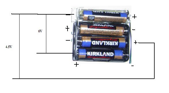
I have 4 batteries in series and I was wondering can i somehow split them into 2 different voltage 4.5v and 6 v
the 4.5v is for micros, ics, and sensors
and the 6 v is for the motor.
My current design works but not simultaniously
when the 4.5v ciruit is connected the 6v turns into 1.5v.
I'm wondering is what I'm asking even possible and if so where would I connect switches?
TY
I'm a noob at these electronics stuff. Sorry.
 

First you have to calculate the power for 6v rail and 4.5v rail.
(Power= current x Voltage) add both the power requirement. Now increase the requirement by another 30% ( thumb rule I use)
now you know the maximum power your circuit may need.

then see how to arrange batteries to achieve to such a power.
Next choose regulators for both your purpose that is 6v and 4.5v with current ratings for your circuit.
That is all.
NOTE: It is easy said than done. but you can try out this. Why not 12v for motor and 5 volt for micros. in that way they became standard and you can get circuits which you can adopt in your projects.

Refer this site for regulated power supply. I guess by suitably modifying you can achieve your goal.
 

Connect four 1.5V batteries in series(-+-+-+-+). So you that get 6V (1.5+1.5+1.5+1.5). You will get 4.5V at positive terminal of third battery and 6V at positive terminal of forth battery. Batteries must meet the current requirement of the motor and IC's otherwise your voltage will drop down.
 

You could do what you suggest, but you can probably run everything from 6V. Check the maximum input voltages for the devices. In any case, if you run motors on them, the batteries will be down to 5V soon enough. Often, when robotics are run from a single battery supply, you get unexpected µC resets when the motors start and pull the voltage too low.
 

**broken link removed**

**broken link removed**

sorry i forgot to mention they were aaa batteries.
Also don't mind the 2 switches. I was being stupid.
So the green wires are suppose to be for the motors.
The blue wires are for the ic's.
Now when I connected the blue ones together the motors only get 1.5 v.
The last battery(white background)
I suspect it's because the blue positive ic wire is turned into ground.
What is wrong with my circuit?
How do i fix it?
 

AAA will probably not be enough for most motors. I'd recommend using the 4 X AAA for the small stuff and a separate pack of AA cells for the motors.
 

4xaa are a bit bit and heavy for my needs.
My robot won't need to run for long.
I just need to show a simple demonstration tomorrow.
I'm wondering if I soldered something wrong?
 

i am not sure about your arrangement. Just see whether you are able to maek out anything out of this connection and cross check whether you have done the same way.


**broken link removed**

black showing prebuilt connection
red showing the connection I made.
i couldn't find a flat 4xaaa case so i built my own.
the bottom 3 black ones are original
mine is the added top white one.
Did I add mine to the wrong side>?
 

I am not still clear with your new representation.

Were you not able to visually check your connections as how i have put in my previous picture?
 

mine is hooked up differently then yours.
but from the way the casing is designed. I think it's kind of impossible to do it your way.
 

Your battery connections are correct. I can't tell what's going on with the switches and their connections. How are the batteries?
 
Last edited:

voltage at 5.93 v and 4.46 v
 

well as far as i can get ! i think that the connections are OK as u r saying u r getting 5.93 and 4.46 V ... the problem is when motor is on the uC doent on or probably gets rest ! thats a clear indication that ur pattery pack doesnt meet the power requiremeents and when motor is on it draws more power at the expense of voltage drop!
 

the problem is when both ciruits are up and running.
The 4.5 v one is ok.
but the 6 v one turns into 1.5v.
so indivually they run at 6v and 4.5v
when i hook both ciruits up it's 1.5 v and 4.5v

---------- Post added at 02:14 ---------- Previous post was at 02:11 ----------

my hypothesis is that the positive blue wire is acting as a negative and the 1.5 v is pulling only from the top white battery.
 

why should the blue wire (+of 4.5V) act as a negative for 6V when it is not at all connected to the 6V circuit which is the motor. The motor should get the same ground as the 4.5V Ground which is at the bottom of the lowest battery. The things shoud work pretty simple. Not sure what's wrong in thid.
 

hmm, when i connect the two green, 6v and measure the 2 blue i get negative
perhaps the blue is being used as negative?
**broken link removed**
 

Status
Not open for further replies.

Similar threads

Part and Inventory Search

Welcome to EDABoard.com

Sponsor

Back
Top