Continue to Site

Welcome to EDAboard.com

Welcome to our site! EDAboard.com is an international Electronics Discussion Forum focused on EDA software, circuits, schematics, books, theory, papers, asic, pld, 8051, DSP, Network, RF, Analog Design, PCB, Service Manuals... and a whole lot more! To participate you need to register. Registration is free. Click here to register now.

1:4 Wilkonson Power Divider using CST

Status
Not open for further replies.

denizduran

Member level 2
Joined
Sep 14, 2021
Messages
48
Helped
0
Reputation
0
Reaction score
1
Trophy points
8
Activity points
463
I am trying to replicate the 1:4 wilkonson power divider attached to this post. Not enough information is given regarding the dimensions, that is why I could not design it. How can I design the exact same circuit without knowing the dimension? I am going to use the design as a feed network for a metasurface antenna.

Screen Shot 2021-09-13 at 22.32.43.png


Screen Shot 2021-09-13 at 19.21.31.png
 

The Length of the Transmission Lines have no importance since the Matching between Input Impedance of the Dividers and Line Impedances. But there may also be a Phase Shift for a particular reason, I don't know.
I believe there is a Step-Matching Purpose between Driving Transmission Lines and Branch Lines so not everything is 50 Ohm . They seem different. I recommend you to design The Wilkinson Dividers first ( I guess you how to do ) then tie them in this configuration.
But this structure is asymmetric so there will be lot of troubles while designing.
 
I am trying to replicate the 1:4 wilkonson power divider attached to this post. Not enough information is given regarding the dimensions, that is why I could not design it. How can I design the exact same circuit without knowing the dimension? I am going to use the design as a feed network for a metasurface antenna.
You do not show your reference or design specs. What do help do you need? Finding a better design reference for a Wilkinson 1:4 metasurface antenna? how to write design specs?
 
The Length of the Transmission Lines have no importance since the Matching between Input Impedance of the Dividers and Line Impedances. But there may also be a Phase Shift for a particular reason, I don't know.
I believe there is a Step-Matching Purpose between Driving Transmission Lines and Branch Lines so not everything is 50 Ohm . They seem different. I recommend you to design The Wilkinson Dividers first ( I guess you how to do ) then tie them in this configuration.
But this structure is asymmetric so there will be lot of troubles while designing.
Hello,

First of all, thank you for your attentive response. There was really no one I could ask and I am having a rough time. I believe that W2 is a lambda multiple of W1 because when I tried reverse engineering this design (trivial solution) and checked the phase difference between the output ports of the top and bottom dividers, there was no phase difference. I designed the same circuit using CST. However, the farfield gain had sidelobes in almost every direction so I knew that the feed network was not working. My Professor suggested that I design this using Ansys Circuit Design, however, as you mentioned, the only thing I know is that the line impedances are 50-ohm and the line which has width w1 is a quarter wave transformer. How would I start my design? I will also attach the IEEE paper I am referring to.

Thank you so much,
Deniz
 

Attachments

  • MetasurfaceAntenna.pdf
    2.6 MB · Views: 184

You will have to dig into all the authors References like [17,18,19,20] and also search for the author's email and request his CST file with the promise to share what you discover and observe the copyrights. (!) You will need to use the same Teflon ceramic woven substrate or consider ceramic.

e.g.
Thickness Reduction and Performance Enhancement of Steerable Square Loop Antenna Using Hybrid High Impedance Surface


Published in: IEEE Transactions on Antennas and Propagation ( Volume: 58, Issue: 5, May 2010 )

Page(s): 1477 - 1485

Date of Publication: 01 March 2010

Print ISSN: 0018-926X

Online ISSN: 1558-2221

INSPEC Accession Number: 11282195

DOI: 10.1109/TAP.2010.2044339

Publisher: IEEE

Sponsored by: IEEE Antennas and Propagation Society
 
the only thing I know is that the line impedances are 50-ohm

Do you mean line in the Wilkinson or line at the Wilkinson output? Wilkinson divider doesn't work with 50 Ohm lines everywhere.

I think it is only drawn that way in the simplified figure in the paper, and does not show all differences in line width.

So I agree with Bigboss: start with designing "normal" Wilkinsons. For the two lines, I agree that phase difference should be n*360° for symmetry reasons.
 
Last edited:
Before you try this , you should understand how to compensate for errors in phased-array attennae from modelling errors in assumptions and understand this method of 3D modelling and have a few iterations of W splitter s parameters realized that match your sim to understand the near field interactions from ray-tracing, skin effects etc..
 
I have a bit given an aye to the paper, Wilkinson Dividers are not directly connected to antenna arrays.The branches are capacitively coupled.. Interesting.
In this case, the Input Impedance of each antenna array group should be well examined to find then Wilkinson Divider can be designed otherwise assuming 50 Ohm Input/Output Impedance will be very erroneous.
Namely, Wilkinson Dividers are generally designed for real impedances but it's also possible to match non-real impedances to the branches with some tricky methods.But it's really difficult..
 
Do you mean line in the Wilkinson or line at the Wilkinson output? Wilkinson divider doesn't work with 50 Ohm lines everywhere.

I think it is only drawn that way in the simplified figure in the paper, and does not show all differences in line width.

So I agree with Bigboss: start with designing "normal" Wilkinsons. For the two lines, I agree that phase difference should be n*360° for symmetry reasons.
Thank you Sir. How do I find the electric delays of the transmission lines? What do you mean by start with designing "normal" Wilkonsons? That is the part that confuses me because in order to be able to create transmission lines width and length, we need the impedance and electric delays and in our case, the electric delays are unknown.
 

BW = 4.2GHz - 6.2GHz.
f0 = 5.5GHz
S11 <= -20dB
Gain = 11-13.3 dB
You will need a much better design to achieve effective low loss and high directivity.
Your link reported in the abstract as follows;

The measurement shows the
impedance bandwidth of 28% (4.41–5.85 GHz)
for |S11| ≤ −10 dB is obtained, and the
boresight gain is greater than 8.4 dBi across the operating band.

--- Updated ---

For those specs, I suggest a Backward Spiral Antenna as a Primary Feed to a Parabolic Reflector Antenna.

Perhaps this may give some insight from a student at my alma mater

These may give the telescopic gain you want.
 
Last edited:
Thank you so much Sir. However, my focus area is implementing metasurfaces to antenna design right now hence I need my antenna to be as shown in the conference paper. In order to obtain the specs givven in the paper, how would I need to design my feed network?
 

I would follow my advice in #7 , unless someone else has better advice.

But just remember for any BP filter that the flat GBW product increases with the square root of the Q of the poles and the Q of the material required for those poles, otherwise errors show up. So you better have precision surface dimensions for phase array and precision low loss dielectrics and excellent kin conductors with all errors accounted for. (I can't prove that, but it has been my anecdotal experience)

But for an active BPF with an integrator built-in, you need a GBW *Q^2 for unity gain BW at fo.

Pls. spell Sir Geoffrey Wilkinson's name correctly.


Consider s11 < -15 dB acceptable.

oh and BTW search thru Google Scholar and Microsoft Academic for your key words https://www.google.com/search?sxsrf...df6CEYQjJkEegQIBhAC&biw=1760&bih=861&dpr=1.09
--- Updated ---

BTW About 195,000,000 results (0.99 seconds)


btw - Urban Dictionary​

https://www.urbandictionary.com › define › term=btw
 
Last edited:

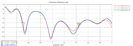
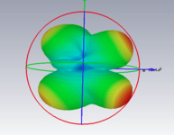
This is my design in CST. I obtain sufficient S11 values for the desired BW however the farfield pattern has side lobes in all directions which contradicts with the purpose of implementing metasurface to antenna design. What can I change (optimize, fine tune) in the feed network to make the pattern better?
 

Attachments

  • Metasurface_Array_Antenna.zip
    56.1 KB · Views: 88
  • Farfield Pattern.png
    Farfield Pattern.png
    203 KB · Views: 100
  • S11 Result after Mesh Analysis.png
    S11 Result after Mesh Analysis.png
    51.3 KB · Views: 124

Status
Not open for further replies.

Part and Inventory Search

Welcome to EDABoard.com

Sponsor

Back
Top