Continue to Site

Welcome to EDAboard.com

Welcome to our site! EDAboard.com is an international Electronics Discussion Forum focused on EDA software, circuits, schematics, books, theory, papers, asic, pld, 8051, DSP, Network, RF, Analog Design, PCB, Service Manuals... and a whole lot more! To participate you need to register. Registration is free. Click here to register now.

А - V meter on ATmega8.

Status
Not open for further replies.
R25 68K, R27 0.01 R
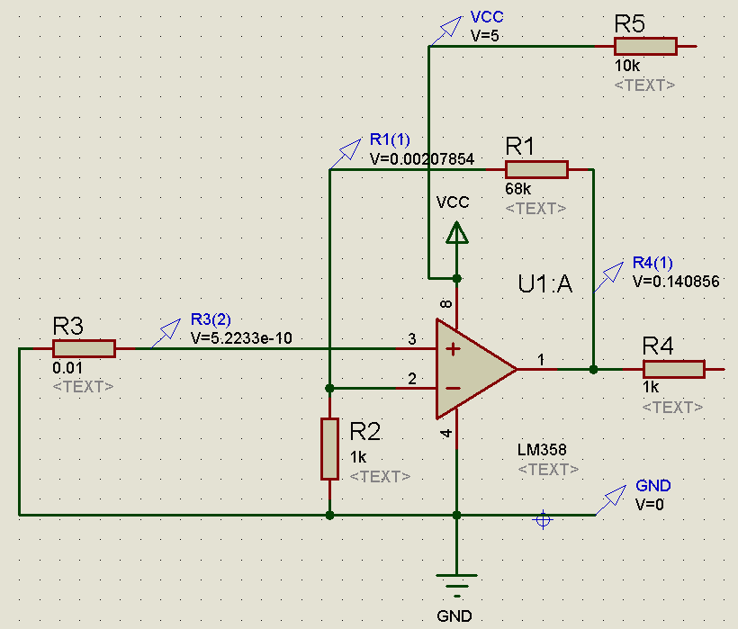
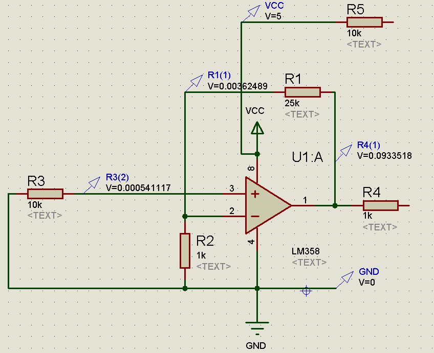
with 0.01R value of R27 R25 value must be around of 24K for 2,5V at output when implemented 10A current on R27.
With shorted input pin3 to ground output pin1 must give close to zero voltage.
Results of modeling LM358 scheme in Proteus:

Pin 21 voltage is 4.5V.
must be 2,45 - 2,5V. Broken TL431? Or its pin1(ref) not shorted to cathode (pin3)?
should i press it for long time to reset the current measuring section.
yes, but it is need to press it for short time before (in this mode LED display blinks).
 
Last edited:

Hi.
My friend got it to work at last. LM358 no good for this application ,at least not for my side. Used MAX495.
The situation is better improved now. R25 is tuned to 6K.
The value of displayed current has just minor problem.
It gives readings a little low than actual load upto 1amp,
And a little higher above 2amps for example at 1.9amps of load it reads 2.1amps.
Further won't go below 0.02 amps. The op-amp this time needs adjustment to be made. Can you help with this situation?

The Aref is now 2.5 volts as it should be. The ref pin must be connected to cathode to work properly. I am using KIA431 model of device. Connecting it to ground will not work it always happens to me as far as I Can remember.
 

Hi again, liteon.
LM358 no good for this application
In my opinion LM358 is not very good for very low voltage, but work. I have done three these AV-meters, LM358 in it works without any visible problems.
It gives readings a little low than actual load upto 1amp,
And a little higher above 2amps for example at 1.9amps of load it reads 2.1amps.
May be R27 changes its resistance from heating?
Locate problem is possible by take a look on dependence of input and output voltage for op amp and input mcu voltage vs value of displayed current for mcu.
 
Last edited:

Thanks a lot dear friend.finally got it working all the way.did a quick rebuild on veroboard.kept all leads at inputs of as short as possible. On bread board the R27 was connected with wires almost 6 inches long to keep it away from board to prevent melting plastic of bread board. Since my requirements for this meter to measure are not very high.the current consumption at output will not go above 3amps.so at full load the resistor got little heated. And its not common horizontal mounting type.It is vertical type with leads under it,designed for use in pc and printer power supplies. Anyways its working properly on veroboard.Its been pleasure to discuss the whole proceeding with you and the help you gave is much appriciated.Again thanks a million.
 

Status
Not open for further replies.

Similar threads

Part and Inventory Search

Welcome to EDABoard.com

Sponsor

Back
Top