Continue to Site

Welcome to EDAboard.com

Welcome to our site! EDAboard.com is an international Electronics Discussion Forum focused on EDA software, circuits, schematics, books, theory, papers, asic, pld, 8051, DSP, Network, RF, Analog Design, PCB, Service Manuals... and a whole lot more! To participate you need to register. Registration is free. Click here to register now.

[SOLVED] ±6x variable gain op-amp

Status
Not open for further replies.
I think I'll calculate the gain based on some real tests, see which brings me better results. Then I'll study some math.
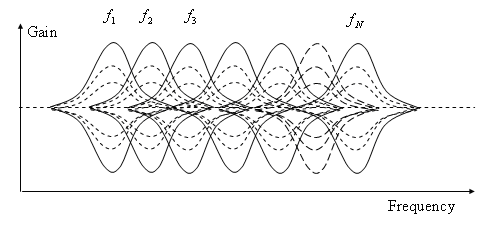
Now, I'm having a doubt about the equalizer bands. I'm not sure how to build the band pass filters... I mean, not really calculating the component values but how do I take the range? For example, the 125Hz BPF, should I make it like a 64Hz HPF and 125Hz LPF, or should I take a range with a central frequency of 125Hz? In this second case, how much band width should I take for each filter?
 

When all bands are set to unity gain, then each band is supposed to be down 3dB at each end of its bandwidth. This will be the frequency which is the geometric mean between the neighboring band. (I believe 3dB means .707 of incoming AC volt level.)

Since the bands are additive, this will result in neutral effect across the spectrum, when all gains are set to unity.

Example, the geometric mean between 125 Hz and 64 Hz (neighboring lower band) is SQRT ( 125 x 64 ) = 89.4 Hz.

So inject a 1V signal at 89.4 Hz.
Set the gain to unity in all bands.
The signal should be .707 V in both the 125 and 64 bands.

You must adjust values so that the Q works out to 1.414, according to the calculator at this link:
 
  • Like
Reactions: T3STY

    T3STY

    Points: 2
    Helpful Answer Positive Rating
It's still a bit unclear to me but I think I got most of it. Thank you all for help ;)
 

Here is a graphic diagram which says about the same thing as my previous post.

It shows gain versus frequency across the bands.

5714477400_1355026814.png


The image was found at:
 

When all bands are set to unity gain, then each band is supposed to be down 3dB at each end of its bandwidth. This will be the frequency which is the geometric mean between the neighboring band. (I believe 3dB means .707 of incoming AC volt level.)

Since the bands are additive, this will result in neutral effect across the spectrum, when all gains are set to unity.

Example, the geometric mean between 125 Hz and 64 Hz (neighboring lower band) is SQRT ( 125 x 64 ) = 89.4 Hz.

So inject a 1V signal at 89.4 Hz.
Set the gain to unity in all bands.
The signal should be .707 V in both the 125 and 64 bands.

You must adjust values so that the Q works out to 1.414, according to the calculator at this link
Sounds plausible at first sight, but doesn't result in a ripple-free neutral characteristic. The calculation for the - 3dB points is right (considering the +/- 45° phase shift), but at the center frequency, the adjacent bands give a higher output. To get a flat characteristic, the filter Q must be considerably reduced, resulting in rather ineffective equalizer. The transition from bandpass to highpass/lowpass at the edges is even more problematic.

The gain diagram in post #24 is belonging to a different equalizer topology, similar to the one discussed in post #5.
 

Sounds plausible at first sight, but doesn't result in a ripple-free neutral characteristic. The calculation for the - 3dB points is right (considering the +/- 45° phase shift), but at the center frequency, the adjacent bands give a higher output. To get a flat characteristic, the filter Q must be considerably reduced, resulting in rather ineffective equalizer. The transition from bandpass to highpass/lowpass at the edges is even more problematic.

Right. My description spoke about unity gain... but it should really apply to anything but that.

Now I realize I was picturing a condition where all knobs are turned up (or down) the same amount. Ideally this should maintain flat response across the spectrum. Which is to say, a flat horizontal line indicating equal gain at all frequencies.

We do not want any frequency to be emphasized. However some overlapping effect between adjacent bands is unavoidable. The best we can do is to make each band show a 3 dB drop where it meets an adjacent band. I believe this is in the definition of a bandwidth.
 

The better way is to implement the flat characteristic is to generate the equalizer output by addition and substraction of band filter signals. Then you don't need to care about exact filter bandwidth in neutral position. Setting all to +6 or - 6dB still gives some ripple, of course.
 

I've been able to find the formula for calculating the output in db, which is 20*log(A) (where A is the amplification). Then, in the equalizer circuit I made before, I've replaced the gain opamp circuit with the one suggested by Brad in post #8, but I've used different values. The circuit is this:
circ.png
Now, I've simulated the circuit in ISIS and works fine. The db formula says that I may have a maximum of 13db boost/cut which is just near 12db. But I'm worried because of the voltage output. The simulation speaker is set to work as a 1kohm speaker with 1V nominal voltage (you can find the ISIS simulation DSN file in the attachments) while the input audio is set to have 1V amplitude. Is it normal/safe to have peaks of 3.27V on the output?
(the yellow indicator is the maximum peak of the input audio)
osc.png

I guess some headphones would break when such a high voltage is applied, so there's something I may be missing here.
 

Attachments

  • circuit.zip
    68.7 KB · Views: 53

But I'm worried because of the voltage output. The simulation speaker is set to work as a 1kohm speaker with 1V nominal voltage (you can find the ISIS simulation DSN file in the attachments) while the input audio is set to have 1V amplitude. Is it normal/safe to have peaks of 3.27V on the output?
(the yellow indicator is the maximum peak of the input audio)

I guess some headphones would break when such a high voltage is applied, so there's something I may be missing here.

Yes, from -12 to +12 dB is a large volt range. From a fraction of a volt to several V.

Its versatility is in letting you have the option of so much range.

It is up to you to be careful how high you set the volume.

Notice that once you have all bands operating, you can use the equalizer as an overall volume booster or reducer.
 

I still don't know if this is safe. I mean, the equalizer will be used with either headphones or as input for a power amplifier. Will the high voltage be a problem to those?
 

I still don't know if this is safe. I mean, the equalizer will be used with either headphones or as input for a power amplifier. Will the high voltage be a problem to those?

Once you start using it and see how it performs, you'll have an idea what settings are correct with your setup.

If any frequency band is weak then you'll want to boost it to a normal level. It won't be too high (unless you hook up the equalizer to a different piece of equipment.)

And you can build in a gain control to make overall adjustments in volume.

As for headphones, they show a wide variation as to what volt levels they need to provide a given volume at your ears.

Have you ever wished your headphones were louder when plugged into your computer? The equalizer will make a big improvement.
 

Status
Not open for further replies.

Similar threads

Part and Inventory Search

Welcome to EDABoard.com

Sponsor

Back
Top