Continue to Site

Welcome to EDAboard.com

Welcome to our site! EDAboard.com is an international Electronics Discussion Forum focused on EDA software, circuits, schematics, books, theory, papers, asic, pld, 8051, DSP, Network, RF, Analog Design, PCB, Service Manuals... and a whole lot more! To participate you need to register. Registration is free. Click here to register now.

±1V differential, ±50V common mode

Status
Not open for further replies.

Smillsey

Member level 5
Joined
Jul 7, 2014
Messages
91
Helped
0
Reputation
0
Reaction score
1
Trophy points
1,288
Activity points
2,121
Hi all

I am somewhat going round in circles here...

I need to design a differential measurement circuit to measure the voltage drop across a coaxial shunt which will have a frequency range of up to 10MHz.

Voltage across the shunt will be +/1V max (at lower frequency)

The common mode can be up to +/-50V

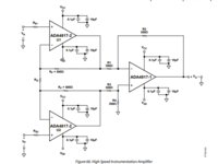
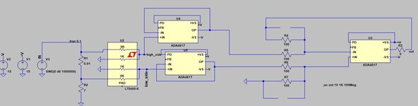
I was thinking about a differential amp based on the LT5400 and 3x ADA4817.

My rails will be +/-5V to the op amps

The shunt resistance is 10mOhms

I tried to simulate a 3 op amp instrumentation amplifier which failed - I will upload it shortly.

I want a 10V/V gain on this part of the circuit.

I tried to simulate a modified version of the ADA4817 datasheet, see attached.

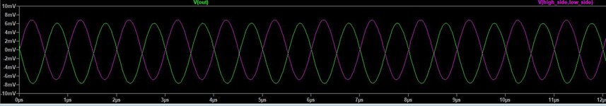
But I just have an oscillator so i am missing something pretty obvious.... Any ideas?
 

Attachments

  • Screenshot 2022-01-06 170109.png
    Screenshot 2022-01-06 170109.png
    42.6 KB · Views: 110
  • Screenshot 2022-01-06 170217.png
    Screenshot 2022-01-06 170217.png
    19.3 KB · Views: 128

Hi,

Please clarify:
* signal: voltage, frequency range, expected precision
(1V across 10mOhms gives 100A, please confirm. Confused: "up to 10MHz", but then "at lower frequency")
* common mode voltage: what frequency range?

*********
Diff amp: it really depends on the expected precision. If you need precision down to DC, then any drift kills the performance.

Klaus

Added:
When I think about it... isn't the real task to measure the current (in opposite to your written task "voltage measurement")
Then there are current transducers, hall sensors ..... (depending on frequency range and precision)
Hey Klaus

Yes there are transducers but they don't have anywhere near the range of frequency i need - I need to differentially measure a 1Hzx~7MHz signal across a 10mOhm resistor

Signal Voltage : Up to 1Vpk/pk across the 10mOhm resistor (coaxial shunt in this case) (100Apk, but only 10Arms MAX)
frequency range : 1Hz ~ 7MHz
Common mode can be +/-48V DC~7MHz

So I need good CMRR, I understand this will degrade as frequency rises.... But initially I just want to simulate a circuit that can cope with +/-48Vpk common mode, able to measure up to 1Vpk/pk differentially up to 7MHz.

DC is not really of interest here, so no worries there.
 

Have you considered an isolated power supply? As the differential voltage is quite low, you could 'float' both inputs by isolating the power supply. I might make returning a result more difficult but you haven't told us how your measurement is used.

Brian.
 
It’s a good point but I cannot isolate this part of the circuit as the data rate is too high and the digital side of the system is already designed - the FPGA-ADC-GAIN stages are not isolated.

I think I will have to work on getting the differential circuit working properly…

I think a modified version of this will work


As I will have +/-5V rails on the ADA4817’s I will need 10:1 attenuation at the very front end so that the +/-48V common mode becomes 4.8V common mode (maybe a bit less as I need to check again the ada4817 datasheet).

This has the downside of attenuating the differential signal too by 10x but I can handle it.

I just could not get my spice to work above 1kHz - the ADA4817’s just oscillated like mad…
 

ADA4817 common mode range is much smaller than 4.8V, you definitely should check the datasheet before sketching a circuit. I also think that it's a bad idea to use a GHz OP for a 10 MHz amplifier. Don't know how your simulation model is oscillating, but the excess bandwidth is probably bringing some problems.

I won't restrict the power supply to +/- 5V before I have a verified solution. CMRR and noise requirements are essential for the design and should be set. You say CM is mainly DC, do you have a specification for CM magnitude versus frequency or a dV/dt limit?
 
+/- 50V CM on a +/- 1V signal, will be tricky for any off the shelf part, two solutions:

for AC signals above 100kHz say a transformer can be designed that will isolate and give the CM attn up to 10MHz easily, if the freq range was 1MHz - 10MHz - even better,

2, Design an analog front end to pair with the IC op-amp ( with +/- 60V rails ) to reduce the CM to that which the IC can handle - great if you have access to the parts and some skill in RF analog design up to 10MHz - this will give reasonable accuracy down to DC however.

3. finally you can divide the signal down with high accuracy compensated resistors ( for the 10 MHz ) so it will fit inside the CM range of an IC op-amp that can handle the freq response required, the 1V will be divided down accordingly ....
 
I missread the CM specification, you said up to 7 MHz, this makes a detailed CMRR spec urgent. Also CM input impedance should be considered, your above sketch has only 5k and won't fit most differential amplifier applications.
 
Last edited:
If you look at RS-422 receivers, these use a resistor divider
network to keep the "internal" common mode within 5V
rails and can manage about a 100mV (spec 400mV)
differential logic threshold. Your bind is supply rails at the
big end and Vio+hysteresis at the little end.

You're asking for about 7X the common mode and an
analog signal (so better than 1/10 the internal signal
I expect).

There are (or were) HV op amps that could take 80V
rails. I was looking at one Harris op amp the other
week, that was on a DLA obsolete parts list. The
trouble with op amps (and HV op amps especially)
is your desire for 10MHz BW. The HV op amps are
built in slower technologies.

There do exist current sense ICs that would appear
meant for what you're after. Your remarks seem
dismissive beyond what I have seen out there. Maybe
you want to undertake a more thorough, modern
parts search.

Things to think about include whether the "pedestal"
voltage is quasi-constant (like VIN) and thus might
allow you to create a high side tracking supply to
feed a high side pinned op amp and current source,
ship the signal as current to the ground domain
and push it onto a matched burden resistor, from
there you can do as you please. A (say) 1K resistor
and 10pF trace capacitance would be well away from
(10X) your 10MHz corner frequency.

This scheme I have seen in IC form fairly recently, but
I do not remember the vendor or P/N.
 

+/- 50V CM on a +/- 1V signal, will be tricky for any off the shelf part, two solutions:

for AC signals above 100kHz say a transformer can be designed that will isolate and give the CM attn up to 10MHz easily, if the freq range was 1MHz - 10MHz - even better,

2, Design an analog front end to pair with the IC op-amp ( with +/- 60V rails ) to reduce the CM to that which the IC can handle - great if you have access to the parts and some skill in RF analog design up to 10MHz - this will give reasonable accuracy down to DC however.

3. finally you can divide the signal down with high accuracy compensated resistors ( for the 10 MHz ) so it will fit inside the CM range of an IC op-amp that can handle the freq response required, the 1V will be divided down accordingly ....
Thanks for the response.

Yes at the moment I am thinking option 3, I have managed to get the circuit simulating correctly now.
--- Updated ---

I missread the CM specification, you said up to 7 MHz, this makes a detailed CMRR spec urgent. Also CM input impedance should be considered, your above sketch has only 5k and won't fit most differential amplifier applications.
I think I will create my own 1Mohm attenuators right at the front end (instead of the LT5400-8 in my first sketch) to drop the common mode to below 4.5V (basically two divide by 10 attenuators which then feed a 3 op-amp instrumentation amp configuration.

The CMRR is nearly very dependent upon the final stage resistor matching.
--- Updated ---

Ok, so my problem in the simulations (with oscillations) was that the ADA4817 did not like the 1k resistors in the feedback chains in the last stage!

I changed to 100ohm and it works, see below a 1MHz input signal with 48V common mode across a 7Ohm load on the low side. The shunt in on the high side....

This isn't final by any stretch but I think the general topology is the way to go.

I am using the ADA4817 because i have other circuits measuring up to 90MHz and I want as little phase shift as possible in those. I could switch to a lower bandwidth opamp here - true....
 

Attachments

  • current_sense_1.JPG
    current_sense_1.JPG
    50.5 KB · Views: 80
  • current_sense_2.JPG
    current_sense_2.JPG
    70.8 KB · Views: 80
Last edited:

Hi,

The CMRR is nearly very dependent upon the final stage resistor matching.
..and capacitance match

let´s say you want the 1M Ohms within 2% then the Xc of the capacitance needs to be within 20M Ohms.
at 7MHz this means about 1fF.

... or is may calculation wrong?

Klaus
 

Hi,


..and capacitance match

let´s say you want the 1M Ohms within 2% then the Xc of the capacitance needs to be within 20M Ohms.
at 7MHz this means about 1fF.

... or is may calculation wrong?

Klaus
Not sure what you mean, you can increase input capacitance across the 1MOhm chain and then have compensation caps with a trim pot at the front end. All diff probes are designed like that
 

Ok, so my problem in the simulations (with oscillations) was that the ADA4817 did not like the 1k resistors in the feedback chains in the last stage!

I changed to 100ohm and it works, see below a 1MHz input signal with 48V common mode across a 7Ohm load on the low side. The shunt in on the high side....
You can use small parallel capacitors to achieve sufficient feedback phase margin. The simulation circuit uses +/-15 V power supply, far beyond ADA4817 limits b.t.w.
I am using the ADA4817 because i have other circuits measuring up to 90MHz and I want as little phase shift as possible in those.
Bandwidth above 10 MHz absolutely needs compensated frontend voltage dividers with C and R CMRR trimming. Look at commercial differential probes for reference. Achievable high frequency CMRR will be still limited. The best we get presently with differential voltage divider probes is marked e.g. by Keysight N2804A probe (300 MHz BW).
1641553414710.png

The CMRR is nearly very dependent upon the final stage resistor matching.
That's why you want additional differential gain in the front-end, if ever applicable. You claimed 1V input range, but the useful shunt output voltage is much lower, unless you design for a huge dynamic range.

My preferred solution for the medium common mode voltage range would be a floating input amplifier followed by a high CMRR differential voltage divider or a special designed high voltage rail amplifier as sketched by Easy peasy. Of course depending on the actual design requirements.
 

Hi,
Not sure what you mean, you can increase input capacitance across the 1MOhm chain and then have compensation caps with a trim pot at the front end. All diff probes are designed like that
True. But if my calculation is correct then we talk about one femtoFarad. This is 0.001pF.
I´d say it´s practically impossible to compensate for this tiny capacitance.
And any mismatch will cause the CMRR to drop at higher frequencies.

Klaus
 

Not sure if I am misunderstanding what you are saying here :)

But the attenuator is not 1MOhm at 7MHz, it becomes a capacitive divider
 

the attenuator is not 1MOhm at 7MHz, it becomes a capacitive divider
Yes, with a crossover frequency between R and C divider somewhere in the middle of the frequency range.
 
Hi,

I just referred to your post#10:
I think I will create my own 1Mohm attenuators
.. not mentioning a capacitive divider nor a "scope like divider".
Also your schematics don´t show the capacitive divider

and it appears that I´m not good in guessing.

But I think I know what you want to do now...

Klaus
 
Hi,

I just referred to your post#10:

.. not mentioning a capacitive divider nor a "scope like divider".
Also your schematics don´t show the capacitive divider

and it appears that I´m not good in guessing.

But I think I know what you want to do now...

Klaus
I should have been clearer

thanks for your advice I got there in the end -
--- Updated ---

Perhaps I missed something but can't you just block the common-mode DC with input capacitors to the differential amp?
Sadly the common mode is a large AC signal, it can be anything from uHz to 7MHz (although won’t be 48V at 7MHz)
 

Status
Not open for further replies.

Similar threads

Part and Inventory Search

Welcome to EDABoard.com

Sponsor

Back
Top