Continue to Site

Welcome to EDAboard.com

Welcome to our site! EDAboard.com is an international Electronics Discussion Forum focused on EDA software, circuits, schematics, books, theory, papers, asic, pld, 8051, DSP, Network, RF, Analog Design, PCB, Service Manuals... and a whole lot more! To participate you need to register. Registration is free. Click here to register now.

[Moved]: Difference between BT138 and BCR12PM Triac's

Status
Not open for further replies.

philicoe

Newbie level 5
Joined
Mar 8, 2017
Messages
9
Helped
0
Reputation
0
Reaction score
0
Trophy points
1
Activity points
83
Hi There,
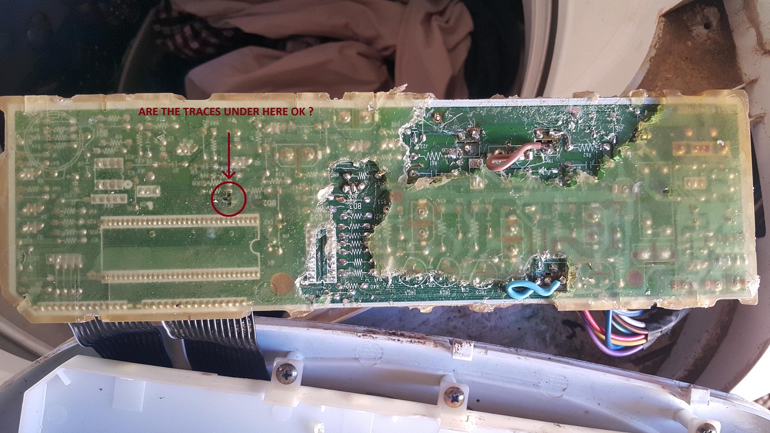
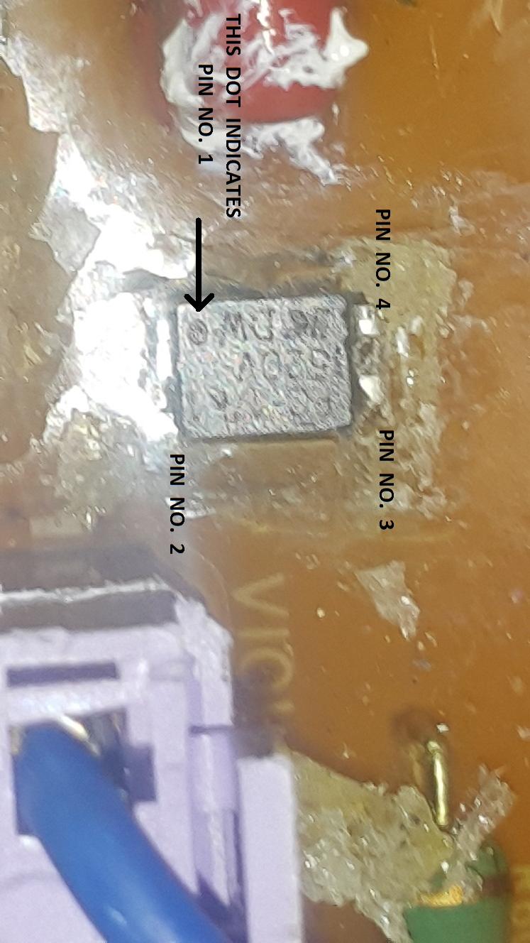
i'm busy fixing my washing machine and it has 2 triacs for driving the tub motor in different directions. The manufacturer has put BCR12PM triacs in for both directions. One of them has given the ghost...

My local supplier has given me a BT138, from what I can see in their specs, the BT138 should be ok.
Both are 12A rated, both at 600 Vdrm, which was the main thing I looked at3.

I have 2 other BTA24 triacs rated at 25A, but won't use them if I can help it.

Can someone confirm this?
 

Re: Difference between BT138 and BCR12PM Triac's

Unlike BCR12PM, BT138 doesn't have insulated tab (screw hole part of the triac). If you just replace BCR12PM by BT138, then MT2 (main terminal 2) of the triac will get electrically connected to heatsink.
Triac BTA12 or BTA16 has insulated tab, so these are better alternatives of BCR12PM. Higher current rated BTA24 should work fine as well.
 

Re: Difference between BT138 and BCR12PM Triac's

Hi There, Yeah i saw about the heat sink...Thanks for the reply..
Eventually used the BTA24, machine is working but no 100% .. The motor is only turning in one direction... .. Checked the motor (split phase ac) and cap..their fine.. something else wrong on pcb....
Theres onky one opto coupler on the board... so I have to trace the circuit to see hoe they configured it
 

Re: Difference between BT138 and BCR12PM Triac's

Hi philicoe,
What is the part number of the optocoupler ?
 

Re: Difference between BT138 and BCR12PM Triac's

Ill check and let you know
 

Re: Difference between BT138 and BCR12PM Triac's

Hi There the Coupler P/N is PC-17k1
 

As there is no suitable optocoupler on the board for driving triacs, so perhaps the triacs are controlled by pulse transformers. There may be a series resistor between pulse transformer's output and triac's gate input and that resistor may also get blown with the blown BCR12PM. Actually what happened to the BCR12PM ? Was it tested and found faulty ? If you upload the picture of the board we can try to trace the circuit too.
 

Hi There,

For your questions, I tested the BCR12's with a DVM and 1 appeared faulty, I replaced both. however, I only see one OptoCoupler on the board which is a PC-17k1 (single coupler IC).
The rest of the circuit is operating as it should i.e. all the other machine functions are ok. Just the motor only spins CW and not CCW.

I have taken quit a bit of pictures for you and have included all inside one zip file accessible on my
**broken link removed**


to make it easier for download.

You will see on the PCB 2 tracks burnt, so I put 2 wires in as a bridge.
Please forgive all the scratch marks on the PCB, was a mission to remove that silicone "epoxy" to see what is going on....

20170311_163617.jpg

20170311_163640.jpg
 
Last edited by a moderator:

I have downloaded the zip file and seen all the pictures. There is no galvanic isolation between triacs and control circuit so it is unsafe to touch any part of the control circuit when power plug is in the socket.

Turn off the machine and take out the power plug from the wall socket and do the checks below.

1. Inside the the violet jack (close to the optocoupler and triacs) there are spring type metallic contacts. It is possible that one of them is damaged when the pcb track is burnt. So make sure using ohm-meter that the violet jack gets proper electrical connection.

2. On the circuit board, check the resistance of triac gate series resistors R41 and R37 (these resistors are connected at pin 15 and pin 14 of ic KID65004). The DMM's readings (100 ohms) should be nearly equal. You don't need to desolder the resistors. This check will make confirm that none of these resistors is open circuited.

3. On the circuit board, check the resistance of gate-MT1 capacitors C30 and C31 (these capacitors are connected between each triac's gate and MT1). The DMM's readings should be nearly equal. You don't need to desolder the capacitors. This check will make confirm that none of these capacitors is short circuited.

4. Pin 2 and 3 of ic KID65004 are the control inputs for the triacs. It seems that the pcb traces between these control inputs and the main microcontroller 87CK14 are damaged. See the attached picture below.


If the problem is not solved yet then you need to measure voltage in running machine at various pins (pin 15,14,2,3 respect to pin 8) of ic KID65004. Depending on the readings we can decide the ic KID65004 is faulty or not. If it is found faulty then we can replace it by either original type or an alternative ic ULN2004. To avoid risk during measurements you can solder one end of a wire at a pin and take out the other end from machine. But first, need to know the results of the above 4 points to be checked.
 

Attachments

  • DTL125_motor-Driver.png
    DTL125_motor-Driver.png
    67.6 KB · Views: 163
  • 20170313_165904 copy.jpg
    20170313_165904 copy.jpg
    556.9 KB · Views: 99

Hi philicoe, the connection of the optocoupler is not correct. On the optocoupler there is a dot mark (see also in datasheet), which indicates pin 1. But in your drawing the dot mark indicates pin 3. See the attached picture below.


In the drawing the part number of the darlington array ic is showing KID65001AP. But actually it is KID65004AP right ?
 

Hi There,

Thanks for the info.

I'll have a look at the board again, the part that looked a lot like a dot is actually an engraving with (C) for copyright...

I could not find the dot or a slot on the side of the chip to indicate pin 1, so I used the next best thing, which is the direction of the engraving of the part number of the I/C. Also when compared to the silkscreen printing on the back of the board, it seems to line up correctly as i drew it.

For the darlington, I may have mad a typing misktake.

But just to be 100% sure, i will have a look at the board when I get a chance.

20170312_183101.jpgoctocpupler.jpg
 

Hi,
In the silkscreen printing on the back of the board, there is a notch mark. According to the notch mark, Pin 1 is supposed to be near the copyright mark (c). See the attached picture below. Here I arrow marked the notch and pin 1.


Hi Ashan,

Apologies for the delayed response. It's been so busy I could only get round to testing out all your suggestions last night.
So what I found was that the KID65004 is the faulty component. I tested all the resistors and caps in question and they all checked out.
So I use a logic probe to test the input and output of the KID65004 and found the input for both directions from the microprocessor to the KID65004 are working as they should, but the one output pin 14 was open circuit, no HIGH or LOW voltage was coming from it, but on 15 all was fine, KID65004 output signal changed properly as the controller pulsed the input.

So I'll replace it this weekend and let you know.

Thanks for all your help thus far. Appreciate. all

Regards
Phil
 

Hi Ashan,

The machine is working fine now, replaced the KID with ULN 2004, but in the end it was a broken track after all of that 8-O.
before I logged this chat , I did actually test the circuit with DVM and it checked out ok.

So after replacing the KID, the motor still only turned only in the one direction. So I checked again using the logic probe and saw that the the logic signals on the 2 gates were the same but not on the output of the ULN.

So what I found was, that there was a small ***** in the track but when pressing on it with the DVM, it made sufficient contact to show conductivity.... however with the logic probe which showed me the weak link.
so s simple wire fixed it. Go figure....

So you learn everyday..
Machine is good as new...
Thanks for everything to everyone
 

Status
Not open for further replies.

Similar threads

Part and Inventory Search

Welcome to EDABoard.com

Sponsor

Back
Top