Continue to Site

Welcome to EDAboard.com

Welcome to our site! EDAboard.com is an international Electronics Discussion Forum focused on EDA software, circuits, schematics, books, theory, papers, asic, pld, 8051, DSP, Network, RF, Analog Design, PCB, Service Manuals... and a whole lot more! To participate you need to register. Registration is free. Click here to register now.

Help with mic preamp and AGC

Status
Not open for further replies.

allison_r

Newbie level 4
Joined
Feb 7, 2017
Messages
7
Helped
0
Reputation
0
Reaction score
0
Trophy points
1
Activity points
101
Hello,

I'd like to build a few mic preamps for my field recordings which usually involve low background noise and low sound levels, I can solder by following circuit drawings however I am not able to design them.

I thought I'd benefit from using a low noise high gain preamp with AGC and a switchable variable resistor to manually set gain those times I won't need AGC.

Since I'd leave equipment out in the wild for a few days (everything would be weather/waterproofed and weather forecasts studied to avoid noisy days such as rainy and windy ones, but those are obviously the least problem) and come back just to retrieve recorded data.

I thought that AGC, even with its obvious limitations, would be more useful to maximize sounds capture rather than setting a certain gain while on the field and leaving it at that level, potentially clipping sound sources coming closer and/or having many ones unrecorded due to too low of a gain set.
The switchable manual gain would come handy when I would record in more forecastable situations, so that I don't have to build another similar circuit over just to include a single function.

I'd couple each one of them (unless there is a fits-all circuit, which I'd gladly use) with a different input (a ceramic piezo transducer for water sounds and either an electret array or RF-condenser mic, due to its higher reliability in high ambient humidity, for air sounds).

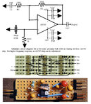
Here is a conceptual diagram I sketched (recorders would be portable battery powered ones, I currently have two, both with 3.5mm TRS jack mic input, 1 with 1.6 kohm impedance and another with 2 kohm impedance, unless I upgrade to something else):
drawing.jpg

After looking for a good preamp I came across this one on a TI's datasheet which apparently has very good reputation (I did add the red line since I thought I won't need phantom power for my current project):
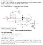
circuit.jpg

I have been suggested this AGC circuit (from a THAT datasheet):
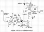
agc.jpg

However I am far from knowing how I should merge them.

Could you please help me? Any suggestion is welcome.

Thank you

Allison
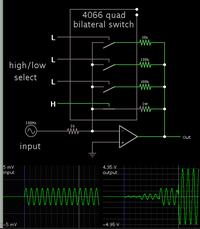
 

Hi,

I thought you might want to see the pdf - I tried it and it works, easy to change Vsupply, no need for an in amp, just 1 suitable op amp and a single supply, it's just an alternative option to compare with, maybe not suitable for recording. What was a lot harder was trying to connect it to a (low) power amplifier circuit into a cheap 8 Ohm speaker... I couldn't comment on automatic gain control circuits.
 

Attachments

  • Single-Supply, Electret Microphone Pre-Amplifier Reference Design TI tidu765.pdf
    960.9 KB · Views: 98
allison_r, what kinds of sounds are you expecting it to pick up?

AGC (ALC) has certain disadvantages you need to be aware of, in particular the time constant of the gain control and it may not work well in some situations. AGC doesn't fix the sensitivity at a constant but correct level, it adjusts it dynamically to try keeping the output level constant under different input sources.

At it's worst, you amplify all the unwanted background noise then get a dead moment if a loud noise is heard, then the background noise resumes. That probably isn't what you want. There may be other methods to prevent overload which let you keep optimized gain but we need some idea of the range and abruptness of the sound over a period of say a few seconds.

Brian.
 
Thank you for your replies.

allison_r, what kinds of sounds are you expecting it to pick up?

AGC (ALC) has certain disadvantages you need to be aware of, in particular the time constant of the gain control and it may not work well in some situations. AGC doesn't fix the sensitivity at a constant but correct level, it adjusts it dynamically to try keeping the output level constant under different input sources.

At it's worst, you amplify all the unwanted background noise then get a dead moment if a loud noise is heard, then the background noise resumes. That probably isn't what you want. There may be other methods to prevent overload which let you keep optimized gain but we need some idea of the range and abruptness of the sound over a period of say a few seconds.

Brian.

For the piezo-based one I'm expecting fishes and marine mammals vocalizations, while for the electret array or RF-condenser based, I'm expecting mostly (but not limited to) bird songs (both night and day), wolves, deer.

They'd basically log everything so that I can later listen to them and analyze spectrums to see which animals were recorded on audio.

I can understand that the constantly optimal gain level set by AGC has some flaws but I thought that since I won't mind "shifting levels" while monitoring biodiversity, it'd be more functional or "failsafe" (particularly if the response time is reasonably short) than setting a gain manually before leaving, just to discover days later that I'd have either used more or less gain most of the time due to either shifting winds, animals going close to equipment or both.

The switchable gain trimmer would be there to have the same circuit double when more acoustically pleasing results rather than datalog ones are expected.

Thank you

Allison
 

Many portable cassette players employ agc when recording. When playing back speech on a typical player, a silent stretch results in background hiss growing in volume over a period of about 3 seconds. A sudden sound causes drop to normal volume in 1 or 2 tenths of a second.
Circuits probably are on the internet.
 
Thanks for the extra info allison_r.

It sounds like what you need is a wide dynamic range rather than AGC. Sounds such bird song which are intermittent in nature can cause real problems to an AGC circuit but how you use the recording afterwards determines whether it is suitable. If you are only analyzing the sound spectrum or communication between species the quality isn't particularly important but if you wanted it to 'sound good' I wouldn't recommend AGC is used. As I see it your options, from best to worst are:

1. A compressor on the mic signal before recording and an expander during playback. This is similar to how Dolby noise reduction works. It gives a more faithful playback while keeping the louder sounds from overloading the recorder.

2. A fast acting AGC circuit (~0.25 seconds) to give a reasonable compromise between level output before 'breathing' (background hiss rising and falling) becomes objectionable.

3. A clipper circuit. This lets you run at higher gain all the time but sets a ceiling loudness level to prevent overload. It does the job but the clipped sounds may be noticably distorted.

Option 1 is most complicated electronically, option3 is cheapest.

Brian.
 
Many portable cassette players employ agc when recording. When playing back speech on a typical player, a silent stretch results in background hiss growing in volume over a period of about 3 seconds. A sudden sound causes drop to normal volume in 1 or 2 tenths of a second.
Circuits probably are on the internet.

Thank you Brad, one of the digital recorders I own has AGC too, however my AGC idea was that it would serve to set gain directly on the low noise low distortion preamp to benefit from its performance, since (I may be wrong), setting an AGC after the preamp would involve another amp (probably a built-in one) which is probably not as performing as the INA217.
I have looked for and found some (such as **broken link removed**), however I have no idea how to merge them so that the AGC sets gain on the preamp since I know nothing about designing circuits and just to give you an idea, I even am puzzled at which function does that optional DC control loop do.

Thanks for the extra info allison_r.

It sounds like what you need is a wide dynamic range rather than AGC. Sounds such bird song which are intermittent in nature can cause real problems to an AGC circuit but how you use the recording afterwards determines whether it is suitable. If you are only analyzing the sound spectrum or communication between species the quality isn't particularly important but if you wanted it to 'sound good' I wouldn't recommend AGC is used. As I see it your options, from best to worst are:

1. A compressor on the mic signal before recording and an expander during playback. This is similar to how Dolby noise reduction works. It gives a more faithful playback while keeping the louder sounds from overloading the recorder.

2. A fast acting AGC circuit (~0.25 seconds) to give a reasonable compromise between level output before 'breathing' (background hiss rising and falling) becomes objectionable.

3. A clipper circuit. This lets you run at higher gain all the time but sets a ceiling loudness level to prevent overload. It does the job but the clipped sounds may be noticably distorted.

Option 1 is most complicated electronically, option3 is cheapest.

Brian.

Thank you Brian, you're welcome. Feel free to ask any other details if it helps.

Any of the solutions you provided would work, I really am open about this since I am not nearly knowledgeable enough to design or merge circuits and just to give you an idea (as also told above to Brad), I even am puzzled at which function does that optional DC control loop do.

Maybe a fast acting (0.25s) AGC circuit (as you've suggested) with a slow recovery (like 5s) could be a compromise for repeated peak patterns such as bird songs if happening within the recovery timeframe.

Otherwise I should probably embrace the idea that I should prepare for lower than optimal gain, set gain on the field before leaving and keep enough headroom for wind blowing against the foam and windscreen.
I record at 16 bit PCM so hopefully there should be enough dynamic range to forgive an audacious gain set.

Thank you

Allison
 

Is there an advantage if you were to make simultaneous recordings, one high volume, one low volume? Or do you already have some sort of duplication? It's making a large bet if you place it all on a sole recording for three days.
 
Is there an advantage if you were to make simultaneous recordings, one high volume, one low volume? Or do you already have some sort of duplication? It's making a large bet if you place it all on a sole recording for three days.

I don't use it yet because I'd have to also double the recording disk space and/or number of recorders used at the same time (unless being able to set different gains on stereo recordings for L/R channels). That'd be a nice solution too.
Really, given my ignorance in circuits design I can't be picky but just be grateful for all of you helping.

Thank you

Allison
 

This idea may already be in your block diagram/ schematics. Create simultaneous soft and intense signals coming from two circuits. Choose in real time which to record. Your detector needs to act at some large threshold voltage.

For a more elaborate version, consider a programmable gain op amp.


The gain ratios are simple to adjust.

The methods above are not necessarily easier to build than the method you are considering, nor do they necessarily provide a more usable audio recording.

I see, thank you. Is there anybody you'd suggest hiring to design this circuit?

Allison

- - - Updated - - -

Edit:

I've been suggested this circuit for the piezo input:

circuit.jpg

It is nice because it includes a high pass filter (yet no AGC or compressor).

It uses two 12V batteries. Could I use just one yet be able to give both + and - voltages?

Gain is set with R2 and R3. Could I replace both of them with a potentiometer to have variable gain?

The high pass frequency is set with R3 and C1. Could I replace the R3 with a potentiometer and add a switch to disable the filter when it isn't needed?

Since I would probably be building just one, I'd like to pick up the best IC for this use so that I can't later think about "I'd have implemented that other IC".

Both AD743 and AD797 are suggested in the diagram. AD743 lists a 2.9 nV/√Hz at 10 kHz while AD797 lists 0.9 nV/√Hz at 1 kHz.
Since I'd be using this in the 3-45 kHz range, does this mean that the AD743 has less signal distortion at upper frequencies (hence the reference to 10 kHz instead of 1 kHz), or are they equivalent?

Thank you

Allison
 

Hi,

Both AD743 and AD797 are suggested in the diagram. AD743 lists a 2.9 nV/√Hz at 10 kHz while AD797 lists 0.9 nV/√Hz at 1 kHz.
Since I'd be using this in the 3-45 kHz range, does this mean that the AD743 has less signal distortion at upper frequencies (hence the reference to 10 kHz instead of 1 kHz), or are they equivalent?
Noise has nothing to do with distortion.
From your given data the AD797 produces less noise. (Because of the lower value and the lower frequency)

0.9nV is very low. There are only a couple of Opamps that can beat this. I know LT1028, LME49990.
I have good experience with LT1028, but the LME looks extrememly good, too.

With all this Opamps the current noise will dominate if source impedance is higher than about 1kOhm.

Klaus
 

Status
Not open for further replies.

Part and Inventory Search

Welcome to EDABoard.com

Sponsor

Back
Top