Continue to Site

Welcome to EDAboard.com

Welcome to our site! EDAboard.com is an international Electronics Discussion Forum focused on EDA software, circuits, schematics, books, theory, papers, asic, pld, 8051, DSP, Network, RF, Analog Design, PCB, Service Manuals... and a whole lot more! To participate you need to register. Registration is free. Click here to register now.

Simple, discrete, audio compressor circuit needed for preamplifier levels

Status
Not open for further replies.

neazoi

Advanced Member level 6
Joined
Jan 5, 2008
Messages
4,122
Helped
13
Reputation
26
Reaction score
15
Trophy points
1,318
Location
Greece
Activity points
36,951
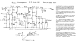
Hi, I need a discrete components circuit for an audio compressor, or automatic audio level control, or audio limiter, or whatever it is called, for my receiver presented at the end of this page **broken link removed**
I want to bring the low level audio signals and the high level audio signals at the same audio level.
I am trying not to attenuate the audio output of it much, so the circuit must have close to unity gain.

I have tried the attached circuit bit it did not have any effect in my receiver, it only attenuated the audio quite a lot.
I have also tried a set of antiparallel germanium diodes before the volume pot.

I think that a good option would be to use an LDR as a variable attenuator or for varying the 2.2M feedback resistor of the final audio amplifier. However these contain cadmium which I do not like much, but if it can't be done other wise better...

Any ideas to try?

- - - Updated - - -

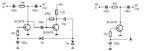
Searching around I found this **broken link removed** maybe this is good and can handle low levels I do not know.

Any ideas?
 

Attachments

  • mini-audio-compressor.gif
    mini-audio-compressor.gif
    32.9 KB · Views: 699
Last edited:

The diodes you tried and the circuit with diodes you found severely distort the audio with clipping, they do not provide automatic gain control.
The horrible regenerative "radio" circuit has very low levels for weak distant signals but has very high levels for strong local signals. A real ordinary radio has AGC for its radio signal, not clipping of its audio signal then a weak signal sounds at the same volume as a strong signal.
 
  • Like
Reactions: neazoi

    neazoi

    Points: 2
    Helpful Answer Positive Rating
The diodes you tried and the circuit with diodes you found severely distort the audio with clipping, they do not provide automatic gain control.
The horrible regenerative "radio" circuit has very low levels for weak distant signals but has very high levels for strong local signals. A real ordinary radio has AGC for its radio signal, not clipping of its audio signal then a weak signal sounds at the same volume as a strong signal.

Why does such a circuit, have to clip?
It could work on audio (not IF) and yet attenuate the high level audio signals instead of clipping it.
A circuit with an LDR for example as an active attenuator, should work fine, if one can generate enough voltage to drive a led. There will be no distortion then.
I am thinking of such a circuit https://4.bp.blogspot.com/_E1J8eYvr...FE/JmPIaLYbGio/w1200-h630-p-nu/Untitled-1.jpg in combination with an LDR instead of the 2.2M feedback resistor in my audio amplifier. It might do the trick?

* By the way, I enjoy listening on this regenerative radio much more than the IC-728 I own. The sensitivity is much more and the audio is REALLY quiet in comparison to the IC-728. I have only heard such low noise audio on $$$ commercial rigs. And this comes from a 30$ homebrew radio. I disagree with the "horrible regenerative" and the "real radio" things you refer above. Also, it is common ammong HAMs that direct conversion receivers (the regenerative is such) have a great sound!
 

Audioguru is quite right but deriving a voltage to control the gain is difficult with the kind of circuit you are using.

I have not tried this but I can't see a reason why it won't work: use the circuit in the link but instead of the LED/LDR, use a photo-mosfet. I'm thinking of something like the PVT412 from International Rectifier, it is designed as an isolated SSR but it must have a linear region where the mosfet resistance could be used instead of the LDR. Dark resistance is around 1,000M and light resistance is <10 Ohms. They are already encased in lightproof resin and the response speed is magnitudes faster than an LDR.

The schematic (elektor?) you show is interesting but I can see it has problems. The actual ALC is achieved by forward biased impedance of D1 and D2 versus the fixed resistance of R1. T2 is a thermal match for T1 to hold it's bias just below conduction point. It would be critical of the transistor and diode types and certainly wouldn't work if you used silicon diodes for example.

Brian
 
  • Like
Reactions: neazoi

    neazoi

    Points: 2
    Helpful Answer Positive Rating
I have not tried this but I can't see a reason why it won't work: use the circuit in the link but instead of the LED/LDR, use a photo-mosfet. I'm thinking of something like the PVT412 from International Rectifier, it is designed as an isolated SSR but it must have a linear region where the mosfet resistance could be used instead of the LDR. Dark resistance is around 1,000M and light resistance is <10 Ohms. They are already encased in lightproof resin and the response speed is magnitudes faster than an LDR.
Brian

It it right to vary the 2.2M feedback resistor in the power amplifier instead of making a variable attenuator at the input? It will save some components, that's why I am asking.

The circuit with the three transistors is able to light up a LED from the static of a hand near it (not touching), so it is quite sensitive. But I think it responds to AC, so there will be LED fluctuations that the aye can't see. So somewhere the AC input must be converted to DC. Where shall I do this?

* The PVT412 is great! It is just my persistence of using discrete components (you do not need to order anything) where I can that makes me not want this.
Some JFETs can be used as variable resistors as well, but I think their resistance range is not much. It would be interesing to use one instead of an ldr though.
 

The trouble with JFETs is they are depletion mode devices, their resistance is lowest with no gate voltage and increases only if the gate is driven below source voltage - you have to turn them off when you really want to turn them on. Using an enhancement mode device works in theory but then you have to reach the gate threshold before their resistance starts to drop so you are back to stabilizing the operating point.

Incidentally, your comments on simple receivers are quite right and their performance can easily exceed more advanced designs if you are prepared to sacrifice user friendliness and their dynamic range. I have started to work on a rather novel design of my own with limited sucess but it has a long way to go before being unleashed to the World. It is quite simple and under manual control it is very sensitive but the final product will have automatic regeneration level control and maybe (it is theoretically possible) a digital frequency display and tuning by rotary control or keypad. I have never seen any design using the same method so it is highly experimental. It should have a good dynamic range and the ability to use real RF AGC to a pre-amplifier stage. The only drawback I've found so far is it stops working when tuned above about 6MHz but I'm sure that can be improved up to VHF with better than 'junk box' components I have used so far.

Brian.
 
  • Like
Reactions: neazoi

    neazoi

    Points: 2
    Helpful Answer Positive Rating
Incidentally, your comments on simple receivers are quite right and their performance can easily exceed more advanced designs if you are prepared to sacrifice user friendliness and their dynamic range. I have started to work on a rather novel design of my own with limited success but it has a long way to go before being unleashed to the World. It is quite simple and under manual control it is very sensitive but the final product will have automatic regeneration level control and maybe (it is theoretically possible) a digital frequency display and tuning by rotary control or keypad. I have never seen any design using the same method so it is highly experimental. It should have a good dynamic range and the ability to use real RF AGC to a pre-amplifier stage. The only drawback I've found so far is it stops working when tuned above about 6MHz but I'm sure that can be improved up to VHF with better than 'junk box' components I have used so far.

Brian.

I remember you have mentioned it as an idea in an older post. Do not forget to send me a message, when you have something to present about it. I would be greatly interested in seeing your design! Many, dream a regen without the extra regeneration knob to tune.
The innovative thing in mine, (actually another's initial idea) is that it can receive single signal, by setting the LSB "out of puff" and at the same time attenuating it. This is achieved in the regenerative stage. I have tested it and it works. The narrow filter helps even more in a way (in narrow modes), to attenuate the close to the carrier image, whereas at the same time allows for a bit more regeneration which improves sensitivity on the USB.
Just to mention, in contrast to your idea, the regeneration knob in this, it the one that allow for other "tricks" such as the ability to receive AM and the ability to operate it as a direct conversion RX (no need to tune the regen at all for this) when needed, or as a "single signal direct conversion" by correct setting of the regeneration control. So I find it advantageous to have it. But it would be great to see your idea.

If I could build a good automatic level control for the audio, this RX would be quite complete to my taste. (apart from a high dynamic range RF preamp :) )
Maybe this will work https://www.ozvalveamps.org/playmaster/compressor.jpg and uses no LDR. This is the page https://www.ozvalveamps.org/playmaster.htm
 
Last edited:

An LDR is too slow to react to loud sounds so they will blast severe distortion until the LDR catches up with the signal level. A Jfet works well when its input level is attenuated.
 
  • Like
Reactions: neazoi

    neazoi

    Points: 2
    Helpful Answer Positive Rating
I suggest you look at an H11Fi fet opto isolator.

https://www.mouser.com/ds/2/149/H11F1M-185284.pdf

These have a fully floating JFET that is hundreds of meg ohms with the LED off. And only a hundred ohms or so with the LED at max.
The distortion is quite low, and up to 30v peak to peak of audio is possible.

Used in shunt mode across a high impedance audio path, it should work pretty well. And its fast.
As its a completely isolated fully floating variable resistance, its very easy to use.
 

Years ago I tried an H11 opto-fet as the AGC for a Wien bridge audio oscillator but its distortion was too high so I added a second one to cancel the distortion of the main one and it worked not too badly. They say it is "distortion-free" but of course it produces distortion since a fet is non-linear.
 

Most of these compressor circuits are for use with speech, where a small amount of distortion will not be noticed.
But I agree a laboratory grade Wein oscillator is a pretty demanding application.

These H11 isolators are amazing things.
I hooked one up between the input and output of a 74HC14 schmidt trigger with a capacitor between the input and ground to make an astable multivibrator. Incredibly it oscillated from well below 1Hz to several MHZ. From memory the capacitor was only 47pF
If you ever need a REALLY wide range VCO, maybe 10 million to one frequency range, nothing else will come anywhere near it.
 

Years ago I tried an H11 opto-fet as the AGC for a Wien bridge audio oscillator but its distortion was too high so I added a second one to cancel the distortion of the main one and it worked not too badly. They say it is "distortion-free" but of course it produces distortion since a fet is non-linear.

It is only the thing that I would love to do it discrete, otherwise I would go for the H11.
How about this one? It uses a jfet to vary the ac gain of the amplifier, but the clipping level and the clipping stiffness can be set.
 

Attachments

  • compressor.png
    compressor.png
    367.6 KB · Views: 178

That schematic seems wrong to me. The symbol for the MPF102 is shown as P-channel but it is an N-channel device and the AGC seems to work in reverse. Highest gain is achieved when the FET is conducting so the AGC has to cut the conduction off to reduce the gain. In that schematic the gain is at maximum with no signal but instead of reducing the gain it forward biases the G-S pins and risks damaging it. The suggested alternative 2N3819 is no better.

Brian.
 
  • Like
Reactions: neazoi

    neazoi

    Points: 2
    Helpful Answer Positive Rating
The undistorted voltage range with typical JFETs can be expected larger than with H11. Particularly if the circuit in #12 is supplemented by a linearizing resistor circuit that superimposes half of Vds to Vgs. You'll find it in most JFET variable resistor circuits. See also e.g. https://www.edaboard.com/threads/129234/#post564116

- - - Updated - - -

The symbol for the MPF102 is shown as P-channel but it is an N-channel device and the AGC seems to work in reverse.

Of course the circuit makes only sense if the rectified DC voltage reverse biases the JFET. So it would either use a PJFET (in contradiction to the type indication) or simply reverse the rectifier polarity. You don't damage a JFET with a few mA forward current, by the way, but the circuit won't work.
 

That schematic seems wrong to me. The symbol for the MPF102 is shown as P-channel but it is an N-channel device and the AGC seems to work in reverse. Highest gain is achieved when the FET is conducting so the AGC has to cut the conduction off to reduce the gain. In that schematic the gain is at maximum with no signal but instead of reducing the gain it forward biases the G-S pins and risks damaging it. The suggested alternative 2N3819 is no better.

Brian.
What if I reverse the two germanium diodes and the smoothing capacitor, so that negative bias is applied to the fet?

- - - Updated - - -

Of course the circuit makes only sense if the rectified DC voltage reverse biases the JFET. So it would either use a PJFET (in contradiction to the type indication) or simply reverse the rectifier polarity. You don't damage a JFET with a few mA forward current, by the way, but the circuit won't work.

We cross posted. Ok, reversing the Ge diodes polarity and the smoothing cap should fix this. I have updated the schematic, please let me know if this is what you refer to.
I hope it works ok at 12V as well.
I think the mpf102 has just been drawn incorrectly by mistake, so I have corrected this as well.

There is a jfet that is purposively used as a variable resistor, I try to remember which one is it.
Ok I have found it. It is the 2n5486
 

Attachments

  • 70598.pdf
    97.3 KB · Views: 80
  • compressor.png
    compressor.png
    330.3 KB · Views: 151
Last edited:

All JFETs are basically suited as variable resistor. Vp and rds however matters.

The linked application note is a good tutorial how to make a low distortion attenuator. Said 2N5486 is a typical RF FET, similar e.g. to MPF102, 2N4416 or BF245. BF245B is the next best replacement.
 
  • Like
Reactions: neazoi

    neazoi

    Points: 2
    Helpful Answer Positive Rating
Hi,

I know you are asking for "simple and discrete".....

But did you ever try those tiny ADAU17xx digital audio processors.
I have a development kit and tried some functions.
It is really fascinating how fast and how simple you can design digital audio processing with an easy to understand graphical development software (SigmaStudio).

I´d say (with a bit of experience) you can design, compile and program the chip within 5 minutes a 3 way crossover. Possible to adjust crossover parameters online.
"Compressor" is a ready block some parameters to adjust it to your needs. Just connect it to inputs and outputs and you can immediately hear the result.

Maybe worth to test it. Maybe not for your current project. Maybe useful in the laboratory to find out the right parameters.

...and ... no, I don´t have a benefit, if someone buys such an IC. I just find it´s a modern way to design signal processing circuits.

Klaus
 
That schematic seems wrong to me. The symbol for the MPF102 is shown as P-channel but it is an N-channel device and the AGC seems to work in reverse. Highest gain is achieved when the FET is conducting so the AGC has to cut the conduction off to reduce the gain. In that schematic the gain is at maximum with no signal but instead of reducing the gain it forward biases the G-S pins and risks damaging it. The suggested alternative 2N3819 is no better.

Brian.
The circuit at post #12 did not work for me.

It is funny that the much simpler circuit attached here (on the right hand side) managed to achieve almost full volume reduction when point "A" was connected to +12v. Additionally, it only attenuated the signal very little, when point "A" was left floating. It is nice because it is simple and does not use any LDR.

However, the complete circuit on the left, did not work ok, I could not achieve enough voltage out of the diodes, only a few mV.
Any ideas of what can I do?
All I need is to convert this low level audio into high level and rectify it, to achieve a higher voltage, so that the attenuator transistor on the right image, can be driven.
 

Attachments

  • ALC.jpg
    ALC.jpg
    31.1 KB · Views: 240

Status
Not open for further replies.

Similar threads

Part and Inventory Search

Welcome to EDABoard.com

Sponsor

Back
Top