Continue to Site

Welcome to EDAboard.com

Welcome to our site! EDAboard.com is an international Electronics Discussion Forum focused on EDA software, circuits, schematics, books, theory, papers, asic, pld, 8051, DSP, Network, RF, Analog Design, PCB, Service Manuals... and a whole lot more! To participate you need to register. Registration is free. Click here to register now.

PIC18F2520 External Interupt work at VSS signal

Status
Not open for further replies.

nis2311

Member level 2
Joined
Nov 19, 2016
Messages
52
Helped
0
Reputation
0
Reaction score
0
Trophy points
6
Activity points
501
I want to make Microcontroller to enable interrupt when Gnd is connected to INT0 (RB0) Microcontroller.
but my code is working only when 5 v or VDD given to INT0 (RBO).
My code is Below
Code:
void interrupt extern()
{ 
if(INT0IE && INT0IF)
{
RC0=1;
}
void main() 
{
ADCON0=0x00;
ADCON1=0x0F;
PORTA=0X00;
PORTB=0X00;
PORTC=0X00;
PORTA=0X1F;
TRISB=0x03;
TRISC=0X00;
PEIE=1;		//Enable Peripheral Interrupt
GIE=1;		//Enable INTs globally
INT0IE=1;
INTEDG0=1;
while(1);
}

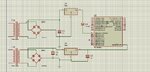
A push button is connected to RB0 and ground. Pullup is added at RB0 to VCC.

Give me solution to find it ..................to work interrupt when VSS signal given.
 

You would want to review the meaning of INTEDG0 in the PIC datasheet.
 

i TRIED
INTEDG0=0;
BUT SAME OUTPUT...........
 

How are you determining which edge is actually triggering the interrupt? Simulation or real circuit?

A real push-button will most likely generate both edges on contact closure as well as contact open by bounce effects.
 

I am connecting VSS from sensor to RB0. If the sensor gives 5 volt means PIC work in normal program, If the sensor output is 0 Volt I want to run INTERRUPT program..........Let me help me.....
 

Zip and post your complete project files and also circuit. Proteus circuit is preferred.
 

I am attaching my program in zip format.
In proteus working well but in hardware not working.............
 

Attachments

  • Ext Int.rar
    110.2 KB · Views: 72

If the sensor output is 0 Volt I want to run INTERRUPT program
Sounds like a different specification. Interrupt on falling edge means the interrupt procedure will be triggered once when the pin changes from 1 to 0.
 

Post actual hardware circuit. Also show PCB layout.
 

My main aim is that , the sensor is external circuit if the circuit losses the power or power down i want to run interrupt program in my PIC controller.
5 volt is taken from the circuit and given to the RB0.
If the external circuit losses the power , interrupt program want to run.
 

External circuit GND and PIC GND should be connected.
 

All same GND connection only.........
 

Show your external circuit.

- - - Updated - - -

In ISR you are setting RC0 = 1 which is wrong. For PIC18F you have to use

Code:
LATC0 = 1;

INTEDG0 should be 0 and not 1 for falling edge detection.


For output you have to use LATx. You have used PORTx registers. make changes in code. Also _XTAL_FREQ XXXXXXXX is missing in the code. You have to define it for the device to work properly.
 
Last edited:

I attached my circuit
1st Power supply for Interrupt
2nd Power supply for PIC
 

Attachments

  • ccc.jpg
    ccc.jpg
    226.4 KB · Views: 99

Bad circuit. 10k resistor missing in MCLR circuit. Also needed for INT0 circuit a pull-down resistor.
 

Hi,

Additionally the "supply for interrupt" forces undefined current into the INT pin when the microcontroller is not supplied.

Better use an additional bjt with two resistors at base and one pullup at collector.

Klaus
 

It will never work for the reasons stated already. Consider what is at the INT pin when the power is removed from TR1, you get a slowly decaying voltage from the regulator but the pin is isolated by D1, it will 'float' and if it generated an interrupt at all it would be randomly timed. A pull-down resistor will fix that issue. Consider that the pin alone draws negligible current so you are also relying on the internal current leakage of U1 to drop the voltage anyway.

If you want to test for AC failure, a far better method would be to monitor the transformer output and sense for missing cycles.

Brian.
 

I have tried using pulldown resistor also.But same condition only
I attached circuit image also
 

Attachments

  • ckt.jpg
    ckt.jpg
    216.5 KB · Views: 92

Use a 1000 uF and 100nF at input and output of the LM78xx regulators.
 

Hi,

Use a 1000 uF and 100nF at input and output of the LM78xx regulators.

The recommendations before say to make it faster, but those big capacitors makes it even slower.

Klaus
 

Status
Not open for further replies.

Similar threads

Part and Inventory Search

Welcome to EDABoard.com

Sponsor

Back
Top