Continue to Site

Welcome to EDAboard.com

Welcome to our site! EDAboard.com is an international Electronics Discussion Forum focused on EDA software, circuits, schematics, books, theory, papers, asic, pld, 8051, DSP, Network, RF, Analog Design, PCB, Service Manuals... and a whole lot more! To participate you need to register. Registration is free. Click here to register now.

UART RX TX LED Driver using Op-Amp

Status
Not open for further replies.

jstefanop

Member level 2
Joined
Nov 9, 2011
Messages
48
Helped
0
Reputation
0
Reaction score
0
Trophy points
1,286
Activity points
1,789
Im trying to build a circuit which flashes LEDs when there is data transmission on the lines. Instead of using transistors I saw an example of an op-amp circuit that can be used to light the LEDs since this is much simpler design and I can use a single dual op-amp chip to drive both RX and TX LEDs.

This is the schematic I based my design from:

broken link removed

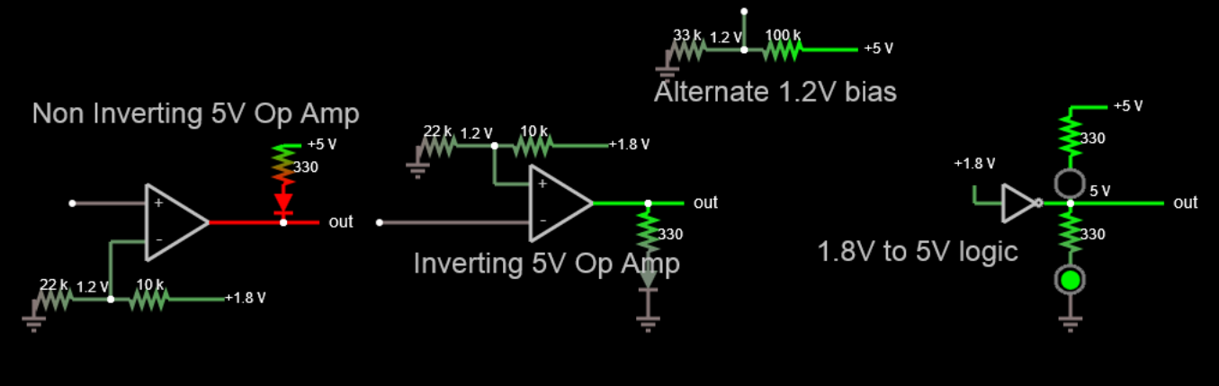
This is exactly how I wired my circuit...only difference is that I have a 1uF cap in parellel with the Vcc line. This in theory should light the LEDs when TX/RX line go low. Problem is that as soon as I apply Vcc the diodes light up even though both RX and TX are idle (high).

What am I missing here? Im using the LMV358 dual op-amp, and Vcc is 5v and TX/RX lines are 1.8v if that makes a difference. Does Vcc also need to be 1.8v for this to work?
 
Last edited by a moderator:

Remove positive feedback and bias Vin(+) with 1 or 2 diodes with pullup to Vcc. or R ratio.

For RS232 the threshold is between this but close to 2 diode drops or 1.3V


It depends on slew rate of Vcc and noise level and resolution of short bursts you may want to stretch.
 

Remove positive feedback and bias Vin(+) with 1 or 2 diodes with pullup to Vcc. or R ratio.

For RS232 the threshold is between this but close to 2 diode drops or 1.3V


It depends on slew rate of Vcc and noise level and resolution of short bursts you may want to stretch.

Not sure what you mean...what is currently wrong with the circuit that the Op Am is lighting the LEDs when TX/RX lines are at 1.8v? This is not for RS232...UART interface is through CP2104 USB to UART chip that controls an ASIC...rx tx lines run at 1.8v, and the Op-Amp is using 5v supply line to drive the LEDs

When TX is idle its at 1.8v, so IN- = 1.8v and IN+ should be at 0v so no output should be occurring and LED should be off...when TX is transmitting it goes to 0v so IN+=IN- = 0v and the op amp should turn on at this state and drive the LED on.

Obviously my logic must be wrong since the LED is always on.
 

WHen you have unity positive feedback you have 100% hysteresis, so IN- must go BELOW 0V for output to go high and visa versa IN- must exceed 5V to drive output low (OFF). Bad idea. not possible.

CHoose no feedback ( cut line) and threshold of 1.2V for IN(+)


Obviously my logic must be wrong since the LED is always on.

all logic chips are analog with a threshold, so when using Op Amp as a logic chip , understand the source impedance and input threshold and load.

For that matter a good 1.8V AND buffer chip can drive the LED direct with Anode to ground or simply a 1.5V FET with suitable RdsOn.

Dont need an Op Amp., Just use a logic AND/OR buffer gate to drive LED low from 1.8V logic with a series silicon diode active low to Cathode of LED.

ESR of buffer may be around 50 Ohms depending on Vol/Iol=ESR (RdsON)

5V- 1.8V-0.6V=2.6V which is not enough to see much light from Blue, Green or WHite LED which vary from 2.9 ~3.6
5V-3.2-0.7=2.1V so 210Ohms for 10mA in series.

Then if you subtract ESR of 1.8V logic driver at Vol you end up with 160 Ohms or so

0V <1.8V Logic> --|<|--------/\/\/\---------|<|----+5V

- - - Updated - - -

(actually with output swing great than input swing >> 100% hysteresis, thus stuck ON.
 

im not going to pretend I understand half of what you said, but it sounds like for the Op Amp to work you need a voltage at the IN+ terminal thats is less than the 1.8v coming in at IN-? This will turn the output off and when IN- falls below IN+ output will be on?

Reason I'm using an Op Amp is because UART line has very low current capability (under 100ma) so if I'm driving two LEDs when both lines are active thats could be up to 20-40ma of current being drawn from the TX/RX lines by the LEDS, which could cause coms issues. This is why I wanted to drive the LEDs from 5v source power instead of the 1.8v UART line.

Would the buffer gate with diode your describing solve this issue as well? Any suitable schematics of what your describing online? I saw lots of examples using transistors, but the Op Amp seemed the most straight forward.
 

I guess you did not read the datasheet for the LMV358 opamp. Its maximum output sourcing current (when its output goes high) is only 5mA which will make an LED appear fairly dim.

I agree than your 100% positive feedback is causing your circuit not to work:
1) When the output is high then the (+) input connected to it is also high.
2) Then for the output to go low the (-) input must be higher than the (+) input voltage that is not allowed with the opamp and does not happen with your input signal.

Well in the current configuration the Op Amp is supplying the full current that the LED can draw with the resistor I have (220 ohms, so about 15ma). The LEDs are pretty bright...if thats the case then I guess I completely burned out the Amp lol.

Guess back to the drawing board on how to run these LEDs without using an OpAmp and not draw current from the RX/TX lines
 

Hi,

OPAMPs are made for regulating purpose, so both inputs usually have the same voltgae. This is not the case in your circuit.

I recommend to use comparators instead. They are made for switching applications.

***
But for your circuit i agree with Brad:
For that matter a good 1.8V AND buffer chip can drive the LED direct with Anode to ground or simply a 1.5V FET with suitable RdsOn.

Klaus
 

If the opamp makes your LED bright enough then use it without any positive feedback or add only a little positive feedback for a small hysteresis. Then bias the (+) input at a voltage that is halfway between the input high voltage and the input low voltage.
 

I can see I have to draw the answers for you.

Your circuit looks like an inverting voltage follower but wrong. It's non-inverting and that wont work.
To decide when to enable the LED, you must know the logic threshold , which for LV logic is ~1.2V so a Reference voltage is needed.
THese are 3 ways to do the same thing.
R choose for only 5 to 10mA depending on colour, which for a small indicator is all you need.
3188663800_1446238497.png

Using Ohm's Law [Vcc - Vf(LED)]/R= I_led
 

Hi,

But for your circuit i agree with Brad:
Just recognised it was SunnySkyguy, not Brad. Sorry.

Klaus
 

I can see I have to draw the answers for you.

Your circuit looks like an inverting voltage follower but wrong. It's non-inverting and that wont work.
To decide when to enable the LED, you must know the logic threshold , which for LV logic is ~1.2V so a Reference voltage is needed.
THese are 3 ways to do the same thing.
R choose for only 5 to 10mA depending on colour, which for a small indicator is all you need.
3188663800_1446238497.png

Using Ohm's Law [Vcc - Vf(LED)]/R= I_led

Thank you for the very detailed response...that makes much better sense now. Only question I have is where would the output be connected? Im guessing for the non inverting op amp it would have to be ground, but would this not be bad during the LED off state since output will be at 5v and will have a short circuit to ground?
 

OUT is clearly shown to be the output of the opamp, not ground. Why would you short the output to ground?

So it would only be connected to the cathode of the LED? How would the LED light since there is no connection to ground when output goes to 0V? It look like it would just be floating, unless when IN- = 0v and IN+ is 1.2v then output gets connected to ground of Op Amp internally and current flows from LED into Op Amp?
 

In the non-inverting opamp, it is obvious that the anode of the LED is connected to +5V through a 330 ohm current-limiting resistor and when the output of the opamp goes low it drives the cathode of the LED almost to ground to make it light.
Maybe you are confusing 0V with ground. They are the same, but ground is simply a common 0V it is not earth's ground.

You said it backwards:
1) IN- is shown to be +1.2V and it NEVER goes to 0V.
2) The input IN+ is never +1.2V, it is either 0V or +logic high.
 

Thank you for the very detailed response...that makes much better sense now. Only question I have is where would the output be connected? Im guessing for the non inverting op amp it would have to be ground, but would this not be bad during the LED off state since output will be at 5v and will have a short circuit to ground?

Each input is on the left, which is universal for schematics.
 

In the non-inverting opamp, it is obvious that the anode of the LED is connected to +5V through a 330 ohm current-limiting resistor and when the output of the opamp goes low it drives the cathode of the LED almost to ground to make it light.
Maybe you are confusing 0V with ground. They are the same, but ground is simply a common 0V it is not earth's ground.

You said it backwards:
1) IN- is shown to be +1.2V and it NEVER goes to 0V.
2) The input IN+ is never +1.2V, it is either 0V or +logic high.

Yea thats what i meant...ok got it thanks again for the very helpful responses! I will breadboard this up and see how it works!

The only thing I'm concerned about is that I'm running uart at 115k baud so the LED on state might be too quick for it to visibly light up...(transmissions are 112B for TX and 8B RX so looking at under a millisecond)...would it be easy to add some sort of "delay" on this circuit to make it stay "on" longer?
 

Your baud rate is much too fast for the very slow LMV358 opamp. Make a digital data detector that drives the opamp with a DC voltage whenever there is data.
 
Your baud rate is much too fast for the very slow LMV358 opamp. Make a digital data detector that drives the opamp with a DC voltage whenever there is data.

I might have a different solution that removes the OpAmp altogether. I just figured out that the UART chip can configure GPIO pins for LED status, problem is the UART IO bus is running at 1.8v which is too low to drive any LED.

Im thinking of connecting one end to 3.3v and the other end to the 1.8v GPIO pin with 200ohm resistor in between. When TX/RX is idle voltage difference will be 1.5v so not enough to drive the LED on, when TX/RX is active GPIO pin will go to 0v which will light the LED.

This will obviously work during the GPIO 0v state, but I'm concerned when its 1.8v would this work or would it be bad connecting two different voltage supplies with an LED like that?
 

Status
Not open for further replies.

Similar threads

Part and Inventory Search

Welcome to EDABoard.com

Sponsor

Back
Top