Continue to Site

Welcome to EDAboard.com

Welcome to our site! EDAboard.com is an international Electronics Discussion Forum focused on EDA software, circuits, schematics, books, theory, papers, asic, pld, 8051, DSP, Network, RF, Analog Design, PCB, Service Manuals... and a whole lot more! To participate you need to register. Registration is free. Click here to register now.

[SOLVED] Deviation from expected behavior of sallen key opamp

Status
Not open for further replies.

mamech

Full Member level 3
Joined
Nov 9, 2010
Messages
176
Helped
0
Reputation
0
Reaction score
0
Trophy points
1,296
Activity points
3,135
Deviation from expected behaviour of sallen key op amp

hello


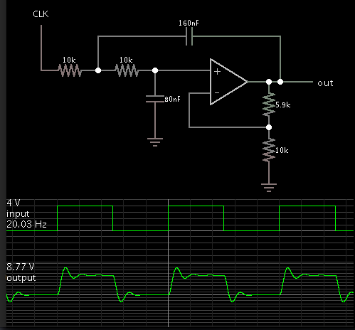
I am trying to make a demonstration for electrical dept. students and to show them a response of a real second order system, and for some reasons I chose sallen key. I built it on bread board. R1= 10k, R2 = 100k, C1=100uf, C2=1uf.

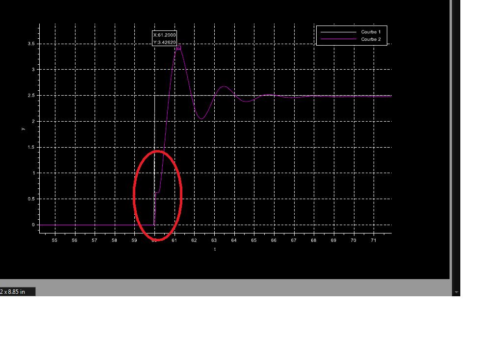
when I give square wave (from arduino) input I get a response that look similar to second order, but with some strange behaviour in the rising curve in the beginning (look at attachment).

I made some simulation in the following site (**broken link removed**), but it gives me a normal curve of second order system, without the deviation that appears in the hardware implemented system.


can anyone tell me why this strange behaviour occurs?

thanks
 

Attachments

  • response.pdf
    18.3 KB · Views: 180

Re: Deviation from expected behaviour of sallen key op amp

What kind of op-amp are you using ? What about the power supply, is it dual or single ?
I see you have large capacitors, then I think you used polarized type. The feedback capacitor, especially at the beginning, when the oscillations are large, can see both an higher voltage at the terminal connected to the output or at the terminal connected to the resistors. This means if you use a polarized capacitor it could experience reverse polarization causing "strange" phenomena.
It's also better to use a dual voltage supply.
 
  • Like
Reactions: mamech

    mamech

    Points: 2
    Helpful Answer Positive Rating
Re: Deviation from expected behaviour of sallen key op amp

I use LM358 opamp. and with single supply, actually I took the supply from arduino itself (5 volts).

and yes, all capacitors that I used are polarized.

regarding using dual supply, I do not think it is the cause of the problem. as you noticed, the discharge happens normally, the problem apprears only in charging , so I think it may be as you said, something related to the nature of electrolytic polarized capacitors.

but this means, that to have a correct performance with sallen key, a man needs to use non polarized capacitors?
 

Re: Deviation from expected behaviour of sallen key op amp

What you are showing is an underdamped response, with a Damping ratio ζ < 0.707

How did you calculate your resistor/capacitor values? What cutoff frequency you require?
 

Re: Deviation from expected behaviour of sallen key op amp

What you are showing is an underdamped response, with a Damping ratio ζ < 0.707

How did you calculate your resistor/capacitor values? What cutoff frequency you require?

yes the damping ratio is about 0.173925271309, according to the site.

I used the site that I have mentioned for estimation of values. and I did not need any certain cutoff frequency, my main objective is to make an underdamped second order system with noticeable slow oscillation to show it to the students with a live example on arduino (I had to use large capacitors to make the Oscillation can be shown , because the arduino library that I am using has limitation about 1 sample every 0.01 second ).
 

Re: Deviation from expected behaviour of sallen key op amp

I made a simulation which displays similar ringing. The capacitors are mismatched.


Re: Deviation from expected behaviour of sallen key op amp

You can try to scale the capacitors to 10u, 100n both ceramic type, just to see if the problem disappear. The frequency of the oscillations should be low enough to allow a correct reconstruction by arduino.
 

Re: Deviation from expected behaviour of sallen key op amp

Your circuit has a very high Q of almost 3 times so it has a huge overshoot, it almost oscillates and it rings like a bell.
A Butterworth response has no overshoot and has a Q of 0.707 times. Its resistors usually have the same value and the feedback capacitor has double the value of the capacitor to ground.
 

Re: Deviation from expected behaviour of sallen key op amp

@audiguru , @BradtheRad

It seems that I did not define my problem well. my problem is not with overshoot, actually I chose the values to so I have overshoot! I deal with this circuit as a second order underdamped "system", not as "a filter" . I am using the results to teach the students that difference between the second order overdamped and underdamped system.


my problem is not with overshoots at all, my problem is with the area marked with red circle here:


I have never seen a second order system that rise suddenly and sharply, and then it tends to behave as any ordinary 2 order system (takes the S shape in during its rising, etc....)

- - - Updated - - -

You can try to scale the capacitors to 10u, 100n both ceramic type, just to see if the problem disappear. The frequency of the oscillations should be low enough to allow a correct reconstruction by arduino.


I hoped that this could work, but in the equation that determines if zeta >1 or <1, it is a function in C1 only and R1 and R2 (and implicitly in ω0, which is function in C1,C2,R1,R2). so may be I can do this scaling by lowers C1, but I will need to increase R1 and R2 greatly. it worth trying, may be capacitors are the cause of this weird behaviour
 

Re: Deviation from expected behaviour of sallen key op amp

You are feeding the circuit with the fast rising edge of a square wave. The rise time of the first oscillation cycle is the same 1 division as the rise times of the second and third oscillation cycles.
The little blip in the trace at Y=0.6 is probably caused by the crossover distortion in an LM358 opamp.
 

Re: Deviation from expected behaviour of sallen key op amp

Be sure about:
1. Proper opamp supply decoupling
2. using capacitors with low ESR (ceramic ones for example)
3. Provide good DC operating point for opamp (i.e. middle of supply)
4. ensure small signal operation - if on your plots y axis is scaled in volts, 2.5V of input step results in large signal behavior - additional slewing, changing DC operating points affecting stability
5. using opamps stable in gain=1 operation mode,
6. et cetera
 

Re: Deviation from expected behaviour of sallen key op amp

I did an LTspice simulation of you circuit but the initial glitch for a step input was only about 26mV, so I'm not sure what's causing the glitch.

One possibility is from the op amp starting at 0V saturation (due in the input offset).
Try starting the input step from an initial DC value of about 0.5V and see if that makes a difference.
You can also achieve that by connecting a 1 meg resistor between the +5V supply and the "+" op amp input (junction of R2 and C2).
 

Re: Deviation from expected behaviour of sallen key op amp

Here is my explanation:

It is the feedback capacitor which is responsible for this effect.
What happens after injecting a pulse into the input?
Before the operational amplifier - together with the feeback loop - can react upon this rising pulse (due to the involved time constants) the rising edge of the pulse is transmitted through the empty feedback capacitor directly to the output of the opamp and causes a corresponding voltage drop across the finite opamp output resistance.
And with a very small time lag the whole system works as desired and we can observe the expected 2nd-order step response.

By the way: This S+K filter has another unwanted effect, which also is caused by this feedback capacitor: For frequencies far beyond the cut-off frequency, the magnitude rises again and causes a rather bad attenuation behaviour of this specific lowpass circuit. It is the same effect: When the opamp output voltage approaches zero, the direct path through the feedback cap produces a voltage across the output resistance (tale effect).
 
  • Like
Reactions: mamech

    mamech

    Points: 2
    Helpful Answer Positive Rating
Re: Deviation from expected behaviour of sallen key op amp

.................
It is the feedback capacitor which is responsible for this effect.
What happens after injecting a pulse into the input?
Before the operational amplifier - together with the feeback loop - can react upon this rising pulse (due to the involved time constants) the rising edge of the pulse is transmitted through the empty feedback capacitor directly to the output of the opamp and causes a corresponding voltage drop across the finite opamp output resistance.
................
I also considered that as a possible cause of the glitch, but the open loop output impedance would have to be over 3kΩ for the observed 0.6V glitch from a 2.5V input pulse into the circuit 10kΩ input resistor.
That seems a little high for the LM358 op amp.
The TI data sheet (Figure 43) shows a value of less than 500Ω at 3MHz frequency (maximum frequency plotted).
 

Re: Deviation from expected behaviour of sallen key op amp

I also considered that as a possible cause of the glitch, but the open loop output impedance would have to be over 3kΩ for the observed 0.6V glitch from a 2.5V input pulse into the circuit 10kΩ input resistor.
That seems a little high for the LM358 op amp.
).

I didn`t check the SPICE model - what about an inductive part at the output?
 

Re: Deviation from expected behaviour of sallen key op amp

You never stated how the waveforms in post #1 and post #9 have been exactly obtained. Recorded with an USB oscilloscope?

I don't see how they could be achieved with LM358 in the given circuit. Can we presume that all capacitors are discharged at t=60? Or is there a hidden forerun?
 

Re: Deviation from expected behaviour of sallen key op amp

I didn`t check the SPICE model - what about an inductive part at the output?
Possible but I doubt the inductance would be that high.

I'd like to see the OP try my suggestion in Post #12 to see if that helps.
 

Re: Deviation from expected behaviour of sallen key op amp

A possible explanation for the voltage step would be that a negative input voltage has been applied before t = 60, forcing the non-inverting OP input to -0.6V (substrate diode limited) and precharges C1 and C2 respectively.
 

Re: Deviation from expected behaviour of sallen key op amp

You can try to scale the capacitors to 10u, 100n both ceramic type, just to see if the problem disappear. The frequency of the oscillations should be low enough to allow a correct reconstruction by arduino.


really thanks for the effort of everyone to recognize the source of the problem. I did as albbg said, and I scaled down the caps to 100n and 10n, and I made resistances to be both 5.1 mega . the good news that the response is perfect now and it resembles really a second order underdamped system , and now I am sure that using polar capacitors are not the best choice in opamp applications, and also I noticed that even in pure RC circuit without opamp, the polar capacitor behaves a little bit differently in discharging .

The bad news now is that there is DC shift in the whole response which has unknown source!

please look:
strange 3.jpg

I checked the circuit many times. I even replaced the ceramic capacitors and I returned the old ones (the polar capacitors with large values), the DC offset disappeared, and the glitch appeared again!

can any one tells me why such DC offset appears now?

- - - Updated - - -

You never stated how the waveforms in post #1 and post #9 have been exactly obtained. Recorded with an USB oscilloscope?


not exactly, there is a library on scilab that enables using arduino with their xcos (similar to simulink in matlab). arduino here is used as kind of slow but simple data aquisition card.
 
Last edited:

Re: Deviation from expected behaviour of sallen key op amp

THere are some design rules to get expected results.

1) never exceed output current ( ok here but marginal for some CMOS Op Amps )
2) Never use polarized caps more than -10% of rated voltage. THey are too leaky and with sufficient mA will blow.
3) Never use electrolytics if you can use ceramics.
4) ALways compare both step polarities. Yours was probably reverse polarized during the early part of the +ve output pulse.
5) Always check input bias current and balance input R's to null Iio*Rin mismatch. THis becomes more obvious as R in put increases. i.,e. dont connect one side to ground and have the other side connected to a large R.

This is why you have DC offset.

4) If you intend to operate outside of room temp and need stability choose the appropriate tempco or stability.

5) CHoose an Op AMp that has the common mode input range that suits your requirement, especially for single supply arrangements.

6. Choose an Op Amp with the output swing and realize there are many choices that give tradeoffs for output swing and output driver impedance and thus output current and saturation.
 

Status
Not open for further replies.

Similar threads

Part and Inventory Search

Welcome to EDABoard.com

Sponsor

Back
Top