Continue to Site

Welcome to EDAboard.com

Welcome to our site! EDAboard.com is an international Electronics Discussion Forum focused on EDA software, circuits, schematics, books, theory, papers, asic, pld, 8051, DSP, Network, RF, Analog Design, PCB, Service Manuals... and a whole lot more! To participate you need to register. Registration is free. Click here to register now.

Resonator Driver circuit

Status
Not open for further replies.

pal114525

Member level 5
Joined
May 20, 2015
Messages
87
Helped
0
Reputation
0
Reaction score
0
Trophy points
6
Activity points
717
Hi,

Please see the attachment.
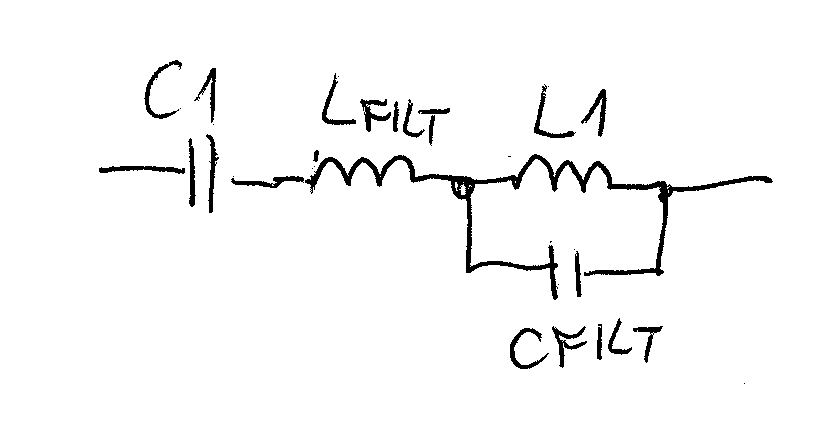
The attached circuit is a resonator driver circuit.
In this circuit simulation, I am using LTSpice.
I am getting the current through the inductor as sinusoidal. But, the voltage across the inductor is not sinusoidal in nature.
Is it a problem of the circuit or problem of the simulator?

Thanks & Regards.
 

Please see the attachment
Indcuctor_voltage.png
 

The 'Add an Image' button is recommended as a fast and reliable way to put an image in your post.

If you are adding a file, then choose 'Manage Attachments'. This forum provides an area for members to keep a collection of files. You may upload files from your computer. You may then attach the files to your posts.

- - - Updated - - -

The image is now visible.
 

Because of the high gain of the oscillator the bridge FETs switch on and off so the voltage would like to be a square wave. The current is what flows when the square wave is fed through a resonant circuit which is the transducer.
Frank
 

Indcuctor_voltage.png

This attachment gives a better view.

Thanks & Regards.

- - - Updated - - -

Hi,

I am getting the sinusoidal output current around 800mA peak value. But, we know that V = L*(di/dt). If, the current is sinusoidal in nature across the inductor, then the voltage across the inductor must be sinusoidal.
Isn't it?

Then, I am not getting the sinusoidal voltage at the inductor. Is there any problem with the circuit or with the simulator?

Thanks & Regards.

- - - Updated - - -

Hi,

I have attached it.

Thanks & Regards.
 

Resonance occurs when reactance of both capacitor and inductor is equal. I think your cap and inductace value is not satisfying resonance criteria. so try to change the inductance value and check.

- - - Updated - - -

If you probe before capacitor and check the frequency it comes around 53.9 kHz. So if you apply the formula i.r for resonance f= 1/2*pi*root(L*C) then you will get 0.018 mH as inductance value. Put this in inductance value and check.
 

Hi,

Thanks for your valuable feedback.
I have checked with the exact value (= 353nF) and it is giving almost the same results ( with little difference in frequency) as with 470nF capacitor.
I have also checked with 330nF capacitor. The result is the same.

Basically, there is no standard value capacitor with 353nF available in the market. Therefore, I have considered two nearest values that are commercially available are 330nF and 470nF.

But, the voltage across the inductor is not in sinusoidal in nature where as the current through the inductor is sinusoidal.

Thanks & Regards.

- - - Updated - - -

Hi,

Thanks for your valuable feedback.
I have used the values for inductor ( = 0.018mH) and for capacitor (= 470nF)
I am not getting the current through the inductor as sinusoidal.

Thanks and Regards.
 

The voltage in your simulation waveform is not the inductor voltage. It's the sum of the inductor voltage and the inverter square wave.

If you want to see the inductor voltage, you should probe it in LTSpice, it's the difference of two node voltages.

The relation between inductor/capacitor current and voltages is a matter of simple network theory, you can derive it. Due to the fact that VL = L*dI/dt, it will enhance harmonic distortion of the current. The requirements for distortion of current and voltages are defined by your application, we can't know it. For most resonant converter applications, the observed waveforms should be O.K.
 

Hi,

Thanks for your valuable feedback.

I've also checked it on breadboard and the voltage across the inductor is not a sinusoidal. It is a distorted waveform from sinusoidal waveform.
Any suggestion for getting a pure sinusoidal wave across the inductor would be highly appreciated.

Thanks & Regards.

- - - Updated - - -

And because of the non-sinusoidal waveform across the inductor, there is NO magnetic field generated.
 

And because of the non-sinusoidal waveform across the inductor, there is NO magnetic field generated.
How can you say this? It's completely wrong.

By design of the circuit, there will be a 24 Vpp squarewave superimposed to to the sinusoidal waveform across the inductor. It can't be avoided without adding filter circuits. What's your application?
 

Hi,

Thanks for your valuable feedback.
I've checked it with a magnetic needle and there was no deflection of the needle.
What type of filter is required to get a pure sinusoidal wave across the inductor?

Thanks & Regards.

- - - Updated - - -

Hi,

I have to create a magnetic field and there will be a deflection on the magnetic needle.

Thanks & Regards.
 

Hi,
Please see the attachment.
In this attachment, the current through the inductor is sinusoidal in nature. But, the voltage across the inductor is not sinusoidal.
Would you please tell me what type of filter is required to remove the distortion and get a pure sinusoidal wave across the inductor?

Thanks & Regards.Indcuctor_voltage.png
 

A LC lowpass (series L, parallel C to the inductor) can do.

But I simply doubt that the present waveform makes a problem for your application. Consider that the magnetic field is generated by the inductor current.
 

A LC lowpass (series L, parallel C to the inductor) can do.

But I simply doubt that the present waveform makes a problem for your application. Consider that the magnetic field is generated by the inductor current.

inductor_voltage_2.png

Hi,

Thanks for your valuable feedback.
Please see the attachment.
The result is the same ( The distorted sinusoidal output)

Thanks & Regards.
 

That's what I meaned:


Hi,

Thanks for your valuable feedback.
what are the values of C1, Cfilt and Lfilt?

Thanks & Regards.

- - - Updated - - -

I have fixed L1 = 0.28mH which basically a coil.
I've only one coil.

Thanks & Regards.
 

Status
Not open for further replies.

Similar threads

Part and Inventory Search

Welcome to EDABoard.com

Sponsor

Back
Top