Continue to Site

Welcome to EDAboard.com

Welcome to our site! EDAboard.com is an international Electronics Discussion Forum focused on EDA software, circuits, schematics, books, theory, papers, asic, pld, 8051, DSP, Network, RF, Analog Design, PCB, Service Manuals... and a whole lot more! To participate you need to register. Registration is free. Click here to register now.

LCD 4 bit PIC asm Help

Status
Not open for further replies.
Joined
Dec 4, 2012
Messages
4,280
Helped
822
Reputation
1,654
Reaction score
791
Trophy points
1,393
Location
Bangalore, India
Activity points
0
I have written a LCD 4 bit C Code. I want to implement it in PIC ASM. I want to know how to write the following C Code in PIC ASM.


Code C - [expand]
1
2
3
4
5
6
7
8
9
10
11
12
13
14
15
16
17
18
19
20
21
22
23
24
25
26
LCD_D4 = (Command & 0x10)?1:0;
LCD_D5 = (Command & 0x20)?1:0;
LCD_D6 = (Command & 0x40)?1:0;
LCD_D7 = (Command & 0x80)?1:0;
LCD_D4 = (Command & 0x01)?1:0;
LCD_D5 = (Command & 0x02)?1:0;
LCD_D6 = (Command & 0x04)?1:0;
LCD_D7 = (Command & 0x08)?1:0;
 
void LCD_Ch(unsigned int row, unsigned int col, char LCDChar)
{
    switch(row){
        case 1:
        LCD_Cmd(0x80 + col-1);
        break;
        case 2:
        LCD_Cmd(0xC0 + col-1);
        break;
        case 3:
        LCD_Cmd(0x94 + col-1);
        break;
        case 4:
        LCD_Cmd(0xD4 + col-1);
        break;
    }
}


- - - Updated - - -

I have written this piece of C Code in ASM for PIC. Is this right?

C Code


Code C - [expand]
1
2
3
4
5
6
7
8
9
10
11
12
13
14
15
16
17
18
19
20
21
22
23
24
25
26
27
28
29
30
31
32
33
34
35
36
37
38
39
40
41
42
43
44
45
46
47
48
49
50
51
52
53
54
55
#define LCD_STROBE {LCD_EN = 1; __delay_us(EN_Delay); LCD_EN = 0; __delay_us(EN_Delay);};
 
void LCD_Cmd(unsigned char Command)
{
    LCD_RS = 0;           // It is a command
 
    LCD_D4 = (Command & 0x10)?1:0;
    LCD_D5 = (Command & 0x20)?1:0;
    LCD_D6 = (Command & 0x40)?1:0;
    LCD_D7 = (Command & 0x80)?1:0;
    LCD_STROBE
    LCD_D4 = (Command & 0x01)?1:0;
    LCD_D5 = (Command & 0x02)?1:0;
    LCD_D6 = (Command & 0x04)?1:0;
    LCD_D7 = (Command & 0x08)?1:0;
    LCD_STROBE
 
    if(Command == 0x01)
    __delay_ms(2);              // Delay for cursor to return at zero position
}
 
 
void LCD_Ch(unsigned int row, unsigned int col, char LCDChar)
{
    switch(row){
 
        case 1:
        LCD_Cmd(0x80 + col-1);
        break;
        case 2:
        LCD_Cmd(0xC0 + col-1);
        break;
        case 3:
        LCD_Cmd(0x94 + col-1);
        break;
        case 4:
        LCD_Cmd(0xD4 + col-1);
        break;
    }
 
    LCD_RS = 1;               // It is data
 
    LCD_D4 = (LCDChar & 0x10)?1:0;
    LCD_D5 = (LCDChar & 0x20)?1:0;
    LCD_D6 = (LCDChar & 0x40)?1:0;
    LCD_D7 = (LCDChar & 0x80)?1:0;
    LCD_STROBE
 
    LCD_D4 = (LCDChar & 0x01)?1:0;
    LCD_D5 = (LCDChar & 0x02)?1:0;
    LCD_D6 = (LCDChar & 0x04)?1:0;
    LCD_D7 = (LCDChar & 0x08)?1:0;
    LCD_EN = 1;
    LCD_STROBE
}


ASM Code

Code ASM - [expand]
1
2
3
4
5
6
7
8
9
10
11
12
13
14
15
16
17
18
19
20
21
22
23
24
25
26
27
28
29
30
31
32
33
34
35
36
37
38
39
40
41
42
43
44
45
46
47
48
49
50
51
52
53
54
55
56
57
58
59
60
61
62
63
64
65
66
67
68
69
70
71
72
73
74
75
76
77
78
79
80
81
82
83
84
85
86
87
88
89
90
91
92
93
94
95
96
97
98
99
100
101
102
103
104
105
106
107
108
109
110
111
112
113
114
115
116
117
118
119
120
121
122
123
124
125
126
127
128
129
130
131
132
133
134
135
136
137
138
139
140
141
142
143
144
145
146
147
148
149
150
151
152
153
154
155
156
157
158
159
160
161
162
163
164
165
166
167
168
169
170
171
172
173
174
175
176
177
178
179
180
181
182
183
184
185
186
187
188
189
190
191
192
193
194
195
cblock
d1
d2
d3
endc
 
 
start
 
LCD_Cmd   MACRO Cmd          ;Cmd is the argument
          
          movlw 0x00;
          movwf LCD_RS
 
          if Cmd & 0x10 
              bsf LCD_D4
          else
              bcf LCD_D4
          endif 
 
          if Cmd & 0x20 
              bsf LCD_D5
          else
              bcf LCD_D5
          endif
 
          if Cmd & 0x40 
              bsf LCD_D6
          else
              bcf LCD_D6
          endif
 
          if Cmd & 0x80 
              bsf LCD_D7
          else
              bcf LCD_D7
          endif
 
          bsf LCD_RS
          call Delay4MHz500us
          bcf LCD_RS
          call Delay4MHz500us
 
          if Cmd & 0x01 
              bsf LCD_D4
          else
              bcf LCD_D4
          endif 
 
          if Cmd & 0x02 
              bsf LCD_D5
          else
              bcf LCD_D5
          endif
 
          if Cmd & 0x04 
              bsf LCD_D6
          else
              bcf LCD_D6
          endif
 
          if Cmd & 0x08 
              bsf LCD_D7
          else
              bcf LCD_D7
          endif
 
          bsf LCD_RS
          call Delay4MHz500us
          bcf LCD_RS
          call Delay4MHz500us
 
          if Command == 0x01
              call Delay4MHz2ms
 
          ENDM
 
 
LCD_Chr MACRO row, col, LCDChar
 
        if row == 1
            LCD_Cmd 0x80 + col-1
        elseif row == 2
            LCD_Cmd 0xC0 + col-1
        elseif row == 3
            LCD_Cmd 0x94 + col-1
        elseif row == 4
            LCD_Cmd 0xD4 + col-1
        endif
 
        bsf LCD_RS
 
        if Cmd & 0x10 
              bsf LCD_D4
          else
              bcf LCD_D4
          endif 
 
          if Cmd & 0x20 
              bsf LCD_D5
          else
              bcf LCD_D5
          endif
 
          if Cmd & 0x40 
              bsf LCD_D6
          else
              bcf LCD_D6
          endif
 
          if Cmd & 0x80 
              bsf LCD_D7
          else
              bcf LCD_D7
          endif
 
          bsf LCD_RS
          call Delay4MHz500us
          bcf LCD_RS
          call Delay4MHz500us
 
          if Cmd & 0x01 
              bsf LCD_D4
          else
              bcf LCD_D4
          endif 
 
          if Cmd & 0x02 
              bsf LCD_D5
          else
              bcf LCD_D5
          endif
 
          if Cmd & 0x04 
              bsf LCD_D6
          else
              bcf LCD_D6
          endif
 
          if Cmd & 0x08 
              bsf LCD_D7
          else
              bcf LCD_D7
          endif
 
          bsf LCD_RS
          call Delay4MHz500us
          bcf LCD_RS
          call Delay4MHz500us
    
        ENDM
        
; Delay = 0.0005 seconds
; Clock frequency = 4 MHz
 
; Actual delay = 0.0005 seconds = 500 cycles
; Error = 0 %
 
Delay4MHz500us
      ;496 cycles
      movlw 0xA5
      movwf d1
Delay4MHz500us_0
      decfsz  d1, f
      goto  Delay4MHz500us_0
 
      ;4 cycles (including call)
  return
 
; Delay = 0.002 seconds
; Clock frequency = 4 MHz
 
; Actual delay = 0.002 seconds = 2000 cycles
; Error = 0 %
  
Delay4MHz2ms
      ;1993 cycles
      movlw 0x8E
      movwf d2
      movlw 0x02
      movwf d3
Delay4MHz2ms_0
        decfsz  d2, f
        goto  label1
        decfsz  d3, f
label1: goto  Delay4MHz2ms_0
 
        ;3 cycles
        goto  label2
label2: nop
 
      ;4 cycles (including call)
  return
 
end


- - - Updated - - -

Here is my new code. Is this right? I have translated C Code to PIC asm. Will the code work especially LCD_Out macro?


Code C - [expand]
1
2
3
4
5
6
7
8
9
10
11
12
13
14
15
16
17
18
19
20
21
22
23
24
25
26
27
28
29
30
31
32
33
34
35
36
37
38
39
40
41
42
43
44
45
46
47
48
49
50
51
52
53
54
55
56
57
58
59
60
61
62
63
64
65
66
67
68
69
70
71
72
73
74
75
76
77
78
79
80
81
82
83
84
85
86
87
88
89
90
91
92
93
94
95
96
97
98
99
100
101
102
103
104
105
106
107
108
109
110
111
112
113
114
115
116
117
118
119
120
121
122
123
124
125
126
127
128
129
130
131
132
133
134
135
136
137
138
139
140
141
142
143
144
145
146
147
148
149
150
151
152
153
154
155
#define LCD_STROBE {LCD_EN = 1; __delay_us(EN_Delay); LCD_EN = 0; __delay_us(EN_Delay);};
 
void LCD_Cmd(unsigned char Command)
{
    LCD_RS = 0;           // It is a command
 
    LCD_D4 = (Command & 0x10)?1:0;
    LCD_D5 = (Command & 0x20)?1:0;
    LCD_D6 = (Command & 0x40)?1:0;
    LCD_D7 = (Command & 0x80)?1:0;
    LCD_STROBE
    LCD_D4 = (Command & 0x01)?1:0;
    LCD_D5 = (Command & 0x02)?1:0;
    LCD_D6 = (Command & 0x04)?1:0;
    LCD_D7 = (Command & 0x08)?1:0;
    LCD_STROBE
 
    if(Command == 0x01)
    __delay_ms(2);              // Delay for cursor to return at zero position
}
 
 
void LCD_Ch(unsigned int row, unsigned int col, char LCDChar)
{
    switch(row){
 
        case 1:
        LCD_Cmd(0x80 + col-1);
        break;
        case 2:
        LCD_Cmd(0xC0 + col-1);
        break;
        case 3:
        LCD_Cmd(0x94 + col-1);
        break;
        case 4:
        LCD_Cmd(0xD4 + col-1);
        break;
    }
 
    LCD_RS = 1;               // It is data
 
    LCD_D4 = (LCDChar & 0x10)?1:0;
    LCD_D5 = (LCDChar & 0x20)?1:0;
    LCD_D6 = (LCDChar & 0x40)?1:0;
    LCD_D7 = (LCDChar & 0x80)?1:0;
    LCD_STROBE
 
    LCD_D4 = (LCDChar & 0x01)?1:0;
    LCD_D5 = (LCDChar & 0x02)?1:0;
    LCD_D6 = (LCDChar & 0x04)?1:0;
    LCD_D7 = (LCDChar & 0x08)?1:0;
    LCD_EN = 1;
    LCD_STROBE
}
 
 
void LCD_Init()
{
    LCD_RS = 0;
    LCD_EN = 0;
    LCD_D4 = 0;
    LCD_D5 = 0;
    LCD_D6 = 0;
    LCD_D7 = 0;
    LCD_RS_Direction = 0;
    LCD_EN_Direction = 0;
    LCD_D4_Direction = 0;
    LCD_D5_Direction = 0;
    LCD_D6_Direction = 0;
    LCD_D7_Direction = 0;
 
    ///////////////// Reset process from datasheet //////////////
    __delay_ms(30);
 
    //Make Data pins zero
 
    LCD_D4 = 0;
    LCD_D5 = 0;
    LCD_D6 = 0;
    LCD_D7 = 0;
 
    //Write 0x3 value on data bus
    LCD_D4 = 1;
    LCD_D5 = 1;
    LCD_D6 = 0;
    LCD_D7 = 0;
 
    LCD_STROBE
 
    __delay_ms(6);
 
    //Make Data pins zero
 
    LCD_D4 = 0;
    LCD_D5 = 0;
    LCD_D6 = 0;
    LCD_D7 = 0;
 
    //Write 0x3 value on data bus
    LCD_D4 = 1;
    LCD_D5 = 1;
    LCD_D6 = 0;
    LCD_D7 = 0;
 
    LCD_STROBE
 
    __delay_ms(3);
 
    //Make Data pins zero
 
    LCD_D4 = 0;
    LCD_D5 = 0;
    LCD_D6 = 0;
    LCD_D7 = 0;
 
    //Write 0x3 value on data bus
    LCD_D4 = 1;
    LCD_D5 = 1;
    LCD_D6 = 0;
    LCD_D7 = 0;
 
    LCD_STROBE
 
    __delay_ms(2);
 
    //Make Data pins zero
 
    LCD_D4 = 0;
    LCD_D5 = 0;
    LCD_D6 = 0;
    LCD_D7 = 0;
 
    //Write 0x2 value on data bus
    LCD_D4 = 0;
    LCD_D5 = 1;
    LCD_D6 = 0;
    LCD_D7 = 0;
 
    LCD_STROBE
 
    __delay_ms(2);
    /////////////// Reset Process End ////////////////
    LCD_Cmd(0x28);    //function set
    LCD_Cmd(0x0C);    //display on,cursor off,blink off
    LCD_Cmd(0x06);    //entry mode, set increment
}
 
void LCD_Out(unsigned int row, unsigned int col, const char *str)
{
    while(*str)
    LCD_Ch(row,col++,*str++);   // print first character on LCD
    row = 1;
    col = 1;
}


Code ASM - [expand]
1
2
3
4
5
6
7
8
9
10
11
12
13
14
15
16
17
18
19
20
21
22
23
24
25
26
27
28
29
30
31
32
33
34
35
36
37
38
39
40
41
42
43
44
45
46
47
48
49
50
51
52
53
54
55
56
57
58
59
60
61
62
63
64
65
66
67
68
69
70
71
72
73
74
75
76
77
78
79
80
81
82
83
84
85
86
87
88
89
90
91
92
93
94
95
96
97
98
99
100
101
102
103
104
105
106
107
108
109
110
111
112
113
114
115
116
117
118
119
120
121
122
123
124
125
126
127
128
129
130
131
132
133
134
135
136
137
138
139
140
141
142
143
144
145
146
147
148
149
150
151
152
153
154
155
156
157
158
159
160
161
162
163
164
165
166
167
168
169
170
171
172
173
174
175
176
177
178
179
180
181
182
183
184
185
186
187
188
189
190
191
192
193
194
195
196
197
198
199
200
201
202
203
204
205
206
207
208
209
210
211
212
213
214
215
216
217
218
219
220
221
222
223
224
225
226
227
228
229
230
231
232
233
234
235
236
237
238
239
240
241
242
243
244
245
246
247
248
249
250
251
252
253
254
255
256
257
258
259
260
261
262
263
264
265
266
267
268
269
270
271
272
273
274
275
276
277
278
279
280
281
282
283
284
285
286
287
288
289
290
291
292
293
294
295
296
297
298
299
300
301
302
303
304
305
306
307
308
309
310
311
312
313
314
315
316
317
318
319
320
321
322
323
324
325
326
327
328
329
330
331
332
333
334
335
336
337
338
339
340
341
342
343
344
345
346
347
348
349
350
351
352
353
354
355
356
357
358
359
360
361
362
363
364
365
366
367
368
369
370
371
372
373
374
375
376
377
378
379
380
381
382
383
384
385
386
387
388
389
390
391
392
393
394
395
396
397
398
399
400
401
402
403
404
cblock
d1
d2
d3
d4
d5
d6
d7
d8
d9
d10
d11
endc
 
 
start
 
LCD_Cmd   MACRO Cmd          ;Cmd is the argument
          
          movlw 0x00;
          movwf LCD_RS
 
          if Cmd & 0x10 
              bsf LCD_D4
          else
              bcf LCD_D4
          endif 
 
          if Cmd & 0x20 
              bsf LCD_D5
          else
              bcf LCD_D5
          endif
 
          if Cmd & 0x40 
              bsf LCD_D6
          else
              bcf LCD_D6
          endif
 
          if Cmd & 0x80 
              bsf LCD_D7
          else
              bcf LCD_D7
          endif
 
          call LCD_STROBE
 
          if Cmd & 0x01 
              bsf LCD_D4
          else
              bcf LCD_D4
          endif 
 
          if Cmd & 0x02 
              bsf LCD_D5
          else
              bcf LCD_D5
          endif
 
          if Cmd & 0x04 
              bsf LCD_D6
          else
              bcf LCD_D6
          endif
 
          if Cmd & 0x08 
              bsf LCD_D7
          else
              bcf LCD_D7
          endif
 
          call LCD_STROBE
 
          if Command == 0x01
              call Delay4MHz2ms
 
          ENDM
 
 
LCD_Chr MACRO row, col, LCDChar
 
        if row == 1
            LCD_Cmd 0x80 + col-1
        elseif row == 2
            LCD_Cmd 0xC0 + col-1
        elseif row == 3
            LCD_Cmd 0x94 + col-1
        elseif row == 4
            LCD_Cmd 0xD4 + col-1
        endif
 
        bsf LCD_RS
 
        if Cmd & 0x10 
              bsf LCD_D4
          else
              bcf LCD_D4
          endif 
 
          if Cmd & 0x20 
              bsf LCD_D5
          else
              bcf LCD_D5
          endif
 
          if Cmd & 0x40 
              bsf LCD_D6
          else
              bcf LCD_D6
          endif
 
          if Cmd & 0x80 
              bsf LCD_D7
          else
              bcf LCD_D7
          endif
          
          call LCD_STROBE
 
          if Cmd & 0x01 
              bsf LCD_D4
          else
              bcf LCD_D4
          endif 
 
          if Cmd & 0x02 
              bsf LCD_D5
          else
              bcf LCD_D5
          endif
 
          if Cmd & 0x04 
              bsf LCD_D6
          else
              bcf LCD_D6
          endif
 
          if Cmd & 0x08 
              bsf LCD_D7
          else
              bcf LCD_D7
          endif
 
          call LCD_STROBE
    
        ENDM
 
LCD_Init  MACRO
            
          bcf LCD_RS
          bcf LCD_EN
          bcf LCD_D4
          bcf LCD_D5
          bcf LCD_D6
          bcf LCD_D7
          bcf LCD_RS_Direction
          bcf LCD_EN_Direction
          bcf LCD_D4_Direction
          bcf LCD_D5_Direction
          bcf LCD_D6_Direction
          bcf LCD_D7_Direction
 
    ;///////////////// Reset process from datasheet //////////////
          call Delay4MHz30ms
 
    ;//Make Data pins zero
          bcf LCD_D4
          bcf LCD_D5
          bcf LCD_D6
          bcf LCD_D7
 
    ;//Write 0x3 value on data bus
          bsf LCD_D4
          bsf LCD_D5
          bcf LCD_D6
          bcf LCD_D7
 
          call LCD_STROBE
 
          call Delay4MHz6ms
 
    ;//Make Data pins zero
 
          bcf LCD_D4
          bcf LCD_D5
          bcf LCD_D6
          bcf LCD_D7
 
    ;//Write 0x3 value on data bus
          bsf LCD_D4
          bsf LCD_D5
          bcf LCD_D6
          bcf LCD_D7
 
          call LCD_STROBE
 
          call Delay4MHz3ms
 
    ;//Make Data pins zero
 
          bcf LCD_D4
          bcf LCD_D5
          bcf LCD_D6
          bcf LCD_D7
 
    ;//Write 0x3 value on data bus
          bsf LCD_D4
          bsf LCD_D5
          bcf LCD_D6
          bcf LCD_D7
 
          call LCD_STROBE
 
          call Delay4MHz2ms
 
    ;//Make Data pins zero
 
          bcf LCD_D4
          bcf LCD_D5
          bcf LCD_D6
          bcf LCD_D7
 
    ;//Write 0x3 value on data bus
          bcf LCD_D4
          bsf LCD_D5
          bcf LCD_D6
          bcf LCD_D7
 
          call LCD_STROBE
 
          call Delay4MHz2ms
    ;/////////////// Reset Process End ////////////////
          LCD_Cmd 0x28    ;//function set
          LCD_Cmd 0x0C    ;//display on,cursor off,blink off
          LCD_Cmd 0x06
      
          ENDM
 
LCD_Out MACRO row, col, *LCDStr 
 
        while *LCDStr
            LCD_Chr row, col, *LCDStr++
        endw
 
        movlw 0x01
        movwf row
        movwf col   
 
        ENDM          
 
LCD_STROBE MACRO
 
          bsf  LCD_RS
          call Delay4MHz500us
          bcf  LCD_RS
          call Delay4MHz500us
 
          ENDM                
 
; Delay = 0.0005 seconds
; Clock frequency = 4 MHz
 
; Actual delay = 0.0005 seconds = 500 cycles
; Error = 0 %
 
Delay4MHz500us
      ;496 cycles
      movlw 0xA5
      movwf d1
Delay4MHz500us_0
      decfsz  d1, f
      goto  Delay4MHz500us_0
 
      ;4 cycles (including call)
  return
 
; Delay = 0.002 seconds
; Clock frequency = 4 MHz
 
; Actual delay = 0.002 seconds = 2000 cycles
; Error = 0 %
  
Delay4MHz2ms
      ;1993 cycles
      movlw 0x8E
      movwf d2
      movlw 0x02
      movwf d3
Delay4MHz2ms_0
        decfsz  d2, f
        goto  label1
        decfsz  d3, f
label1: goto  Delay4MHz2ms_0
 
        ;3 cycles
        goto  label2
label2: nop
 
      ;4 cycles (including call)
  return
 
; Delay = 0.03 seconds
; Clock frequency = 4 MHz
 
; Actual delay = 0.03 seconds = 30000 cycles
; Error = 0 %
 
Delay4MHz30ms
      ;29993 cycles
      movlw 0x6E
      movwf d4
      movlw 0x18
      movwf d5
Delay4MHz30ms_0
        decfsz  d4, f
        goto  label4
        decfsz  d5, f
label4: goto  Delay4MHz30ms_0
 
        ;3 cycles
        goto  label5
label5: nop
 
      ;4 cycles (including call)
  return
 
; Delay = 0.002 seconds
; Clock frequency = 4 MHz
 
; Actual delay = 0.002 seconds = 2000 cycles
; Error = 0 %
 
 
Delay4MHz2ms
      ;1993 cycles
      movlw 0x8E
      movwf d6
      movlw 0x02
      movwf d7
Delay4MHz2ms_0
        decfsz  d6, f
        goto  label6
        decfsz  d7, f
label6: goto  Delay4MHz2ms_0
 
        ;3 cycles
        goto  label7
label7: nop
 
        ;4 cycles (including call)
        return
 
; Delay = 0.003 seconds
; Clock frequency = 4 MHz
 
; Actual delay = 0.003 seconds = 3000 cycles
; Error = 0 %
 
Delay4MHz3ms
      ;2993 cycles
      movlw 0x56
      movwf d8
      movlw 0x03
      movwf d9
Delay4MHz3ms_0
        decfsz  d8, f
        goto  label8
        decfsz  d9, f
label8: goto  Delay4MHz3ms_0
 
        ;3 cycles
        goto  label9
label9: nop
 
        ;4 cycles (including call)
        return
 
; Delay = 0.006 seconds
; Clock frequency = 4 MHz
 
; Actual delay = 0.006 seconds = 6000 cycles
; Error = 0 %
 
Delay4MHz6ms
      ;5993 cycles
      movlw 0xAE
      movwf d10
      movlw 0x05
      movwf d11
Delay4MHz6ms_0
          decfsz  d10, f
          goto  label10
          decfsz  d11, f
label10:  goto  Delay4MHz6ms_0
 
          ;3 cycles
          goto  label11
label11:  nop
 
          ;4 cycles (including call)
          return
 
end

 
Last edited:

Hi,

Thats a lot of code for anyone to go though and check and you have done it in a very different way to most examples I have seen, though no reason why it cannot be done like that

Have you run it on your hardware or in a simulator - does it work ?

There are lots of sites around with Assembly turorials for a 2x16 lcd, heres just one example

Code:
; LcdInit - call this subroutine before using the display. It uses
;           bits 7-1 of PORTB, leaving bit-0 free (although it will
;           be configured as an output).
;
; Lcd_C -   Sends the byte in W as a command to the display. Checks
;           if busy first. 
;
; Lcd_D -   Sends the byte in W as data. Checks for busy first.
;
; Assumes it can call a routine called "delay" with a required
; time delay in mSecs in W. 
; Uses an additional three (3) levels of the stack.
;
; Address of first line on the LCD is 0
; Address of second line is 64
;
; Ron Kreymborg
;******************************************************************

lcd_com	macro	arg1
	movlw	arg1
	call	lcd_c
	endm
	
; Flags -
lcd_Bflg	equ	0
lcd_RSflg	equ	1

; I/O portB - 
lcd_BUSY	equ	7		; input - LCD is busy (0x80)
lcd_R_W		equ	3		; output - LCD Read/Write (0x08)
lcd_RS		equ	2		; output - Register Select (0x04)
lcd_E		equ	1		; output - LCD Enable (0x02)


lcd_init
	clrf	LCDPORT
	movlw	b'00000000'			; all outputs and low to start
	movwf	LCDTRIS
	bcf	lcd_flags,lcd_RSflg
	call	delay15					; 15mSec power up delay		
	movlw	b'00110000'			; 8-bit mode
	movwf	LCDPORT
	call	lcd_clk
	call	delay5					; 4mSec wait
	movlw	b'00110000'			; 8-bit mode
	movwf	LCDPORT
	call	lcd_clk
	call	delay1					; 1 mSec wait
	movlw	b'00110000'			; 8-bit mode
	movwf	LCDPORT	
	call	lcd_clk
	call	delay5					; 4mSec wait
	movlw	b'00100000'			; set for 4-bit
	movwf	LCDPORT
	call	lcd_clk

; Reset sequence is done - initialise for us

	lcd_com	b'00101000'			; 4-bits, 2-lines, 5x7
	lcd_com	b'00001000'			; display off, cursor off, blink off
	lcd_com	b'00001100'			; display on
	lcd_com	b'00000001'			; clear display
	lcd_com	b'00000110'			; increment, no display shift

	return


; Check whether the LCD is busy. Loop until it isn't. When
; it's free, output the byte passed in W, MS nibble first.

lcd_d	bsf	lcd_flags,lcd_RSflg		; set RS flag for data
		goto	lcd_o1
lcd_c	bcf	lcd_flags,lcd_RSflg		; clear RS flag for commands
lcd_o1	movwf	lcd_temp			; save control word
		movlw	b'11110000'			; RB7-4 as inputs for busy
		movwf	LCDTRIS
		movlw	1 << lcd_R_W
		movwf	LCDPORT				; set up for read
	
lcd_o2	bcf	lcd_flags,lcd_Bflg		; assume not busy
		bsf	LCDPORT,lcd_E				; clock high
		nop							; little wait
		btfsc LCDPORT,lcd_BUSY		; busy set?
		bsf	lcd_flags,lcd_Bflg		; yes
		bcf	 LCDPORT,lcd_E				; clock low
		nop							; little wait
		nop
		call	lcd_clk				; get low bits but ignore (for now)
		btfsc	lcd_flags,lcd_Bflg	; was it busy?
		goto	lcd_o2				; yes
		movlw	b'00000000'			; RB7-4 outputs again
		movwf	LCDTRIS
		movf	lcd_temp,w			; get word to send
		call	lcd_o3				; send high nibble
		swapf	lcd_temp,w			; get word again
lcd_o3	andlw	0xf0				; just high bits (clears all control bits)
		movwf	LCDPORT
		btfsc	lcd_flags,lcd_RSflg	; was lcd_RS set?
		bsf		LCDPORT,lcd_RS		; yes
		call	lcd_clk				; write current nibble

		return
	

lcd_clk	bsf	LCDPORT,lcd_E				; pulse E line high
		nop
		bcf	LCDPORT,lcd_E

		return
 

There are no 'if' and 'else' instructions in a PIC so no, it won't work. Those are directives used for conditional assembly and only used to decide which parts of code are to be used in the final program. They play no part in the running of the program whatsoever.

There are several ways to perform logical bit checks, the easiest is to use the btfss and btfsc instructions (there are others in later PICs but you haven't told us which you are using). For example: "if Cmd & 0x80 bsf LCD_D7" would become:
btfsc Cmd, 7
<goto the next instruction>
bsf LCD_7

The other method is to load the comparison value into W (example movlw 0x80) and use the 'andwf Cmd' or 'subwf Cmd' instruction. These will set or reset the Z flag in the STATUS register which you then use to control program flow.

Brian.
 

Here is my working code for LCD 4-bit. It is tested in Proteus and Hardware. I have a problem. I want to print strings. How to do that in asm? My code prints characters.


Code C - [expand]
1
2
3
4
5
6
7
8
9
10
11
12
13
14
15
16
17
18
19
20
21
22
23
24
25
26
27
28
29
30
31
32
33
34
35
36
37
38
39
40
41
42
43
44
45
46
47
48
49
50
51
52
53
54
55
56
57
58
59
60
61
62
63
64
65
66
67
68
69
70
71
72
73
74
75
76
77
78
79
80
81
82
83
84
85
86
87
88
89
90
91
92
93
94
95
96
97
98
99
100
101
102
103
104
105
106
107
108
109
110
111
112
113
114
115
116
117
118
119
120
121
122
123
124
125
126
127
128
129
130
131
132
133
134
135
136
137
138
139
140
141
142
143
144
145
146
147
148
149
150
151
152
153
154
155
156
157
158
159
160
161
162
163
164
165
166
167
168
169
170
171
172
173
174
175
176
177
178
179
180
181
182
183
184
185
186
187
188
189
190
191
192
193
194
195
196
197
198
199
200
201
202
203
204
205
206
207
208
209
210
211
212
213
214
215
216
217
218
219
220
221
222
223
224
225
226
227
228
229
230
231
232
233
234
235
236
237
238
239
240
241
242
243
244
245
246
247
248
249
250
251
252
253
254
255
256
257
258
259
260
261
262
263
264
265
266
267
268
269
270
271
272
273
274
275
276
277
278
279
280
281
282
283
284
285
286
287
288
289
290
291
292
293
294
295
296
297
298
299
300
301
302
303
304
305
306
307
308
309
310
311
312
313
314
315
316
317
318
319
320
321
322
323
324
325
326
327
328
329
330
331
332
333
334
335
336
337
338
339
340
341
342
343
344
345
346
347
348
349
350
351
352
353
354
355
356
357
358
359
360
361
362
363
364
365
366
367
368
369
370
371
372
373
374
375
376
377
378
379
380
381
382
383
384
385
386
387
388
389
390
391
392
393
394
395
396
397
398
399
400
401
402
403
404
405
406
407
408
409
410
411
412
413
414
415
416
417
418
419
420
421
422
423
424
425
426
427
428
429
430
431
432
433
434
435
436
437
438
439
440
441
442
443
444
445
446
;Program:       LCD 4-bit
;Date:          01/06/2013  dd/mm/yyyy
;Author:        Jayanth Devarayanadurga
;MCU:           PIC18F458
;Clock:         4 MHz
 
    list p=18f458
    #include <p18f458.inc>
    
 
    cblock
        d1
        d2
        d3
        d4
        d5
        d6
        d7
        d8
        d9
        d10
        d11
        row
        col
        LCDChar     
    endc
        
#define _LCD_FIRST_ROW          0x80     ;//Move cursor to the 1st row
#define _LCD_SECOND_ROW         0xC0     ;//Move cursor to the 2nd row
#define _LCD_THIRD_ROW          0x94     ;//Move cursor to the 3rd row
#define _LCD_FOURTH_ROW         0xD4     ;//Move cursor to the 4th row
#define _LCD_CLEAR              0x01     ;//Clear display
#define _LCD_RETURN_HOME        0x02     ;//Return cursor to home position, returns a shifted display to
                                         ;//its original position. Display data RAM is unaffected.
#define _LCD_CURSOR_OFF         0x0C     ;//Turn off cursor
#define _LCD_UNDERLINE_ON       0x0E     ;//Underline cursor on
#define _LCD_BLINK_CURSOR_ON    0x0F     ;//Blink cursor on
#define _LCD_MOVE_CURSOR_LEFT   0x10     ;//Move cursor left without changing display data RAM
#define _LCD_MOVE_CURSOR_RIGHT  0x14     ;//Move cursor right without changing display data RAM
#define _LCD_TURN_ON            0x0C     ;//Turn Lcd display on
#define _LCD_TURN_OFF           0x08     ;//Turn Lcd display off
#define _LCD_SHIFT_LEFT         0x18     ;//Shift display left without changing display data RAM
#define _LCD_SHIFT_RIGHT        0x1E     ;//Shift display right without changing display data RAM
 
#define LCD_RS PORTB,0
#define LCD_EN PORTB,1
#define LCD_D4 PORTB,4
#define LCD_D5 PORTB,5
#define LCD_D6 PORTB,6
#define LCD_D7 PORTB,7
#define LCD_RS_Direction TRISB,0
#define LCD_EN_Direction TRISB,1
#define LCD_D4_Direction TRISB,4
#define LCD_D5_Direction TRISB,5
#define LCD_D6_Direction TRISB,6
#define LCD_D7_Direction TRISB,7
 
    org 0x0000
        goto start
 
LCD_Cmd   MACRO Cmd          ;Cmd is the argument
          
          bcf LCD_RS
 
          if Cmd & H'10'
              bsf LCD_D4
          else
              bcf LCD_D4
          endif 
 
          if Cmd & H'20'
              bsf LCD_D5
          else
              bcf LCD_D5
          endif
 
          if Cmd & H'40'
              bsf LCD_D6
          else
              bcf LCD_D6
          endif
 
          if Cmd & H'80'
              bsf LCD_D7
          else
              bcf LCD_D7
          endif
 
          LCD_STROBE
 
          if Cmd & H'01'
              bsf LCD_D4
          else
              bcf LCD_D4
          endif 
 
          if Cmd & H'02'
              bsf LCD_D5
          else
              bcf LCD_D5
          endif
 
          if Cmd & H'04'
              bsf LCD_D6
          else
              bcf LCD_D6
          endif
 
          if Cmd & H'08'
              bsf LCD_D7
          else
              bcf LCD_D7
          endif
 
          LCD_STROBE
 
          if Cmd == H'01'
                call Delay2ms
 
        ENDM
 
 
LCD_Chr MACRO row1, col1, LCDChar
 
    if row1 == .1
        LCD_Cmd H'80' + col1 -.1
    else if row1 == .2
        LCD_Cmd H'C0' + col1 -.1
    else if row1 == .3
        LCD_Cmd H'94' + col1 -.1
    else if row1 == .4
        LCD_Cmd H'D4' + col1 -.1
    endif
        
    bsf LCD_RS
 
    if LCDChar & H'10' 
           bsf LCD_D4
    else
           bcf LCD_D4
    endif 
 
    if LCDChar & H'20' 
           bsf LCD_D5
    else
           bcf LCD_D5
    endif
 
    if LCDChar & H'40' 
           bsf LCD_D6
    else
           bcf LCD_D6
    endif
 
    if LCDChar & H'80' 
           bsf LCD_D7
    else
           bcf LCD_D7
    endif
          
    LCD_STROBE
 
    if LCDChar & H'01' 
           bsf LCD_D4
    else
           bcf LCD_D4
    endif 
 
    if LCDChar & H'02' 
           bsf LCD_D5
    else
           bcf LCD_D5
    endif
 
    if LCDChar & H'04' 
           bsf LCD_D6
    else
           bcf LCD_D6
    endif
 
    if LCDChar & H'08' 
           bsf LCD_D7
    else
           bcf LCD_D7
    endif
 
    LCD_STROBE
    
    ENDM
 
LCD_Init  MACRO
            
          bcf LCD_RS
          bcf LCD_EN
          bcf LCD_D4
          bcf LCD_D5
          bcf LCD_D6
          bcf LCD_D7
          bcf LCD_RS_Direction
          bcf LCD_EN_Direction
          bcf LCD_D4_Direction
          bcf LCD_D5_Direction
          bcf LCD_D6_Direction
          bcf LCD_D7_Direction
 
    ;///////////////// Reset process from datasheet //////////////
          call Delay30ms
 
    ;//Make Data pins zero
          bcf LCD_D4
          bcf LCD_D5
          bcf LCD_D6
          bcf LCD_D7
 
    ;//Write 0x3 value on data bus
          bsf LCD_D4
          bsf LCD_D5
          bcf LCD_D6
          bcf LCD_D7
 
          LCD_STROBE
 
          call Delay6ms
 
    ;//Make Data pins zero
 
          bcf LCD_D4
          bcf LCD_D5
          bcf LCD_D6
          bcf LCD_D7
 
    ;//Write 0x3 value on data bus
          bsf LCD_D4
          bsf LCD_D5
          bcf LCD_D6
          bcf LCD_D7
 
          LCD_STROBE
 
          call Delay3ms
 
    ;//Make Data pins zero
 
          bcf LCD_D4
          bcf LCD_D5
          bcf LCD_D6
          bcf LCD_D7
 
    ;//Write 0x3 value on data bus
          bsf LCD_D4
          bsf LCD_D5
          bcf LCD_D6
          bcf LCD_D7
 
          LCD_STROBE
 
          call Delay2ms
 
    ;//Make Data pins zero
 
          bcf LCD_D4
          bcf LCD_D5
          bcf LCD_D6
          bcf LCD_D7
 
    ;//Write 0x3 value on data bus
          bcf LCD_D4
          bsf LCD_D5
          bcf LCD_D6
          bcf LCD_D7
 
          LCD_STROBE
 
          call Delay2ms
    ;/////////////// Reset Process End ////////////////
          LCD_Cmd H'28'    ;//function set
          LCD_Cmd H'0C'    ;//display on,cursor off,blink off
          LCD_Cmd H'06'
      
          ENDM
 
LCD_Out MACRO row, col, LCDStr 
        local i
        while LCDStr
            LCD_Chr row, col, LCDStr++            
        endw
 
        movlw H'01'
        movwf row
        movwf col   
 
        ENDM          
 
LCD_STROBE MACRO
 
           bsf  LCD_EN
           call Dly500us
           bcf  LCD_EN
           call Dly500us
 
           ENDM
 
    org 0x300
 
start
 
    LCD_Init
    LCD_Cmd H'80'
    
main_loop:
 
    
    LCD_Chr .1,.1,'J'
    LCD_Chr .1,.2,'a'
    LCD_Chr .1,.3,'y'
    LCD_Chr .1,.4,'a'
    LCD_Chr .1,.5,'n'
    LCD_Chr .1,.6,'t'
    LCD_Chr .1,.7,'h'
    LCD_Chr .1,.8,' '
    LCD_Chr .1,.9,'D'
            
    goto main_loop


; Delay = 0.0005 seconds
; Clock frequency = 4 MHz
 
; Actual delay = 0.0005 seconds = 500 cycles
; Error = 0 %
 
Dly500us
      ;496 cycles
      movlw H'A5'
      movwf d1
Dly500us_0
      decfsz  d1, f
      goto  Dly500us_0
 
      ;4 cycles (including call)
  return
 
; Delay = 0.002 seconds
; Clock frequency = 4 MHz
 
; Actual delay = 0.002 seconds = 2000 cycles
; Error = 0 %
  
Delay2ms
      ;1993 cycles
      movlw H'8E'
      movwf d2
      movlw H'02'
      movwf d3
Delay2ms_0
        decfsz  d2, f
        goto  label1
        decfsz  d3, f
label1: goto  Delay2ms_0
 
        ;3 cycles
        goto  label2
label2: nop
 
      ;4 cycles (including call)
  return
 
; Delay = 0.03 seconds
; Clock frequency = 4 MHz
 
; Actual delay = 0.03 seconds = 30000 cycles
; Error = 0 %
 
Delay30ms
      ;29993 cycles
      movlw H'6E'
      movwf d4
      movlw H'18'
      movwf d5
Delay30ms_0
        decfsz  d4, f
        goto  label4
        decfsz  d5, f
label4: goto  Delay30ms_0
 
        ;3 cycles
        goto  label5
label5: nop
 
      ;4 cycles (including call)
  return
 
; Delay = 0.003 seconds
; Clock frequency = 4 MHz
 
; Actual delay = 0.003 seconds = 3000 cycles
; Error = 0 %
 
Delay3ms
      ;2993 cycles
      movlw H'56'
      movwf d8
      movlw H'03'
      movwf d9
Delay3ms_0
        decfsz  d8, f
        goto  label8
        decfsz  d9, f
label8: goto  Delay3ms_0
 
        ;3 cycles
        goto  label9
label9: nop
 
        ;4 cycles (including call)
        return
 
; Delay = 0.006 seconds
; Clock frequency = 4 MHz
 
; Actual delay = 0.006 seconds = 6000 cycles
; Error = 0 %
 
Delay6ms
      ;5993 cycles
      movlw H'AE'
      movwf d10
      movlw H'05'
      movwf d11
Delay6ms_0
          decfsz  d10, f
          goto  label10
          decfsz  d11, f
label10:  goto  Delay6ms_0
 
          ;3 cycles
          goto  label11
label11:  nop
 
          ;4 cycles (including call)
          return
 
LCDStr data "                    "
 
          end


- - - Updated - - -

@betwixt

I am using PIC18F458 and my code is working fine. I want to know how to send strings and print it. I know there are no string type or any data type like int or float. I need an example to implement array or pointer of c code in asm.
 

Attachments

  • 4 bit LCD.rar
    48.1 KB · Views: 66
Last edited:

You have to treat each character individually. There are many ways to manipulate strings but probably the easiest is to use the FSR register. Set the value in the FSR to the start of the string and read the INDF register to pick up the character value. When you have done that, increment the FSR and repeat the operation. If your string is zero terminated (as it is by default in 'C') you can do a simple check for the Z flag being set to tell you when the end of string is reached. The FSR register is analogous to a pointer in 'C', it holds an address which you access through the INDF register, as you increment it you are 'walking' along the characters in the string one by one.

Brian.
 

I did something like this but it is not working.


Code ASM - [expand]
1
2
3
4
5
6
7
8
9
10
11
12
13
14
15
LCD_Out MACRO row, col, LCDStr 
                local i
                
                movlw LCDStr
                movwf FSR
                LCD_Chr row, col, INDF
inc:    incf  FSR,f
        LCD_Chr row, col, INDF
        goto inc
 
        movlw H'01'
        movwf row
        movwf col   
 
        ENDM


I think writing everything as macros will lead you into trouble. You should also bear in mind that a macro is quite different from a subroutine. You write a subroutine once and can call it many times but a macro is expanded to full code each time it is used and put in line with the program. Even small looking programs written with macros can end up being huge in final code.

If you want to follow the present method, you have two problems, the first is that the FSR tegisters are 8 bits wide so they cannot address all RAM locations directly. You will have to use FSR0H and FSR0L as high and low address pointers respectively. Look at the MPLAB help for "HIGH" and "LOW" for assistance in setting the registers to the upper and lower parts of an address.

Your second problems is knowing when the string ends. Either you have to use a distinctive character value, usually zero (as in 'C') or another of your choice. Then each time you read a character from INDF0 you have to check to see if that character is reached, or, if the string length is known you can use a counter to step through it until the end. I'll drop a hint if you want to know string lengths: Place all your strings together and give each a label. The label will hold the address of the string and the length can be calculated by subtracting the name of the label you want from the label of the one following it. You may have to add a dummy label at the end to work out the final strings length. Using zero as a termnator is easiest because there are instruction to test for zero and branch accordingly.

Brian.
 
wp100 can you explain this piece of code. I think this code will do what I want. What is TOSL and TOSH? It calls lcd_d function, instead I want to call my LCD_Chr function or macro. How to do it? I am attaching my files, it is printing some wrong character.


Code ASM - [expand]
1
2
3
4
5
6
7
8
9
10
11
12
13
14
15
16
17
18
19
20
21
22
23
24
25
26
27
28
29
30
31
32
; the PutString sub-routine by Mike McClaren, K8LH
; [url]https://www.electro-tech-online.com/microcontrollers/94132-new-18f-memory-look-up-table-questions.html[/url]
        
;  PutString - print in-line string via Stack and TBLPTR
;
;  string must be terminated with a 0 byte and does not need
;  to be word aligned


PutString
        movff   TOSL,TBLPTRL            ; copy return address into TBLPTR
        movff   TOSH,TBLPTRH    
        clrf    TBLPTRU                 ; assume PIC with < 64-KB
PutNext
        tblrd   *+                      ; get in-line string character
        movf    TABLAT,W                ; last character (0)?
        bz      PutExit                 ; yes, exit, else
        call    lcd_d                   ; print character
        bra     PutNext                 ; and do another
PutExit
        btfsc   TBLPTRL,0               ; odd address?
        tblrd   *+                      ; yes, make it even (fix PC)
        movf    TBLPTRH,W               ; setup new return address
        movwf   TOSH                    
        movf    TBLPTRL,W       
        movwf   TOSL            
        return                          ; to 1st instruction after the string table


;******************************************************************************


Attachments

  • LCD ASM.rar
    54 KB · Views: 59

Look at the data sheet for your PIC in the instrction section. It explains TABLPTR instructions in detail. They are three Table Pointers, one for the low, mid and high addresses (Microchip call them low, high and upper) which can access data tables anywhere in program memory. They also have automatic increment versions of the instructions, similar to ++ and -- in 'C'. They make access to large tables of fixed data much easier to handle but only work in program memory.

Brian.
 
Hi,

TOSL/H are the TOP of STACK registers. Its the STACK that stores the Program Counter address during Calls etc - see the datasheet Memory - Program Counter Section.

Also worth looking at Mike McClarens link as shown in the code -
The subsystem looks more complex then it really is. Basically when the "call PutString" instruction is executed the return address on the stack points to the first character of the in-line string table. The subroutine copies that address into the TBLPTR registers and sends each string table character, up to the null terminator, to your LCD_Char subroutine. Then the subroutine sets the return address on the stack to the address of the instruction following the in-line string table and 'returns' there.


Have not looked at you lcd_char routine as such, but if it works ok then just replace the lcd_d call.
 
@bwtwixt and wp100.

The code doesn't show passing a string as argument to the putstring function. Can you show how to do that?

If I use functions instead of macros then how can I pass arguments to functions?
 
Last edited:

That's up to you! Assembly language has no method for passing arguments, that is the difference between a low level language and a high level language!

Again there are many ways to do this but I would guess easiest is to declare some addresses to carry the address of the variables. You would load the arguments into reserved addresses, then call the function which would retrieve them from those addresses. In 'C' arguments are usually passed on the stack but it can be difficult in some PICs because they have limited stack space.

Brian.
 

@wp100

The K8LH code you gave works fine. I have attached a working code with simulation but my code is not working. why? I have modified K8LH code a little. Just the LCD_D function is changed. Please have a look at both K8LH working code and my code. Both are attached. Tell me what is wrong in my code.

Edit: I am attaching a new version of code. It is displaying blocks on second line when string is passed but not printing characters. At the end of the asm file there are three versions of LCD_D function commented out of which the first 2 versions print character T and P on LCD. I have used the K8LH code which is a working code which is attached in this post. I don't know why it is not working with my code. If I use LCD_PORT and use the LCD_D code commented at the end of the file which sends upper and lower nibbles to PORTB then it works fine but if I try to send single bits to LCD pins it is not working. The same LCD_Chr code works fine. I have modified the LCD_Chr macro in LCD_D function. Please check the v1 file and tell me what is causing the problem.
 

Attachments

  • K8LH.rar
    32.8 KB · Views: 64
  • LCD ASM.rar
    39 KB · Views: 66
  • LCD ASM v1.rar
    54.3 KB · Views: 67
Last edited:

Hi Jayanth,

I put together those lcd examples to help others get going with their code on what can be a difficult area to get right.

As for debugging your long listing with its many directives I just really do not have the time or expertise to quickly spot the error.

Possibly members like Brian, with much sharper minds that me, might be able to quickly identify the cause of the problem.

Also have a read at these lcd turorial which cover every lcd control bit /byte in detail.
http://www.epemag.wimborne.co.uk/resources.htm
 
wp100 just check the LCD_D routine. In LCD_D routine Iif I use something like if 'T' & H'10' ... like that it works but it is not working when W is used.
 

If I ever had a sharp mind it was many years ago - it's quite blunt now!

Jayanth, I think your code needs a complete rewrite using a few subroutines and a lot less macro code. I'm very busy at the moment but I'll see if I can show you some real code later.

Brian.
 
Hi,

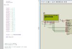
I ran your code and it worked ok for the first line but blocks on the second line.

Added a W before the D and it again worked ok ... ?

Change the data completely and included 22 characters so it overflowed to line 3.

So cannot see a fault as such, though as already said , compared to more typical assembly lcd routines you do seem to still code in a lengthy C fashion.
 

Attachments

  • 2013-06-03 18_51_06-lcd - MPLAB IDE v8.90.jpg
    2013-06-03 18_51_06-lcd - MPLAB IDE v8.90.jpg
    65.6 KB · Views: 79
Sorry Jayanth, I had some problems today and ran out of time. It's just after midnight and I have to start a job at 7am so there isn't time right now to write anything. I'll try again tomorrow but wp100's comment about writing in C fashion is quite right.

Brian.
 
Status
Not open for further replies.

Similar threads

Part and Inventory Search

Welcome to EDABoard.com

Sponsor

Back
Top