Continue to Site

Welcome to EDAboard.com

Welcome to our site! EDAboard.com is an international Electronics Discussion Forum focused on EDA software, circuits, schematics, books, theory, papers, asic, pld, 8051, DSP, Network, RF, Analog Design, PCB, Service Manuals... and a whole lot more! To participate you need to register. Registration is free. Click here to register now.

[SOLVED] Help for IR Data transmitter & decoder by using 12F675 mikroC compiler

Status
Not open for further replies.

bkar

Junior Member level 3
Joined
Nov 1, 2010
Messages
26
Helped
1
Reputation
2
Reaction score
1
Trophy points
1,283
Activity points
1,626
Dear All,

I am new in using micro controller.
I wanted to build a transmitter & receiver by using 12F675 PIC IC and mikroC compiler for programming.

Here is my code for TRANSMITTER.


//***********************************************************************//

Code C - [expand]
1
2
3
4
5
6
7
8
9
10
11
12
13
14
15
16
17
18
19
20
21
22
23
24
25
26
27
28
29
30
31
32
33
34
35
36
37
38
39
40
41
42
43
44
45
46
47
48
49
50
51
52
53
54
55
56
57
58
59
60
61
62
63
64
65
66
67
68
69
70
71
72
73
74
75
76
77
void InitMain()
{
   TRISIO = 0x1F;
   GPIO.GP5 = 0;             //Define default outputs
   ANSEL = 0x00;             //All I/O digital
   CMCON = 0x07;            //Disable comparator
   OPTION_REG = 0x00;     //Enable pull-ups
   
}
void pulseIR(unsigned int pulse)
{                                 //38khz IR modulation
  GPIO.GP5=0;
  while (pulse > 0)
  {
      GPIO.GP5=1;               
      Delay_us(5);              
      GPIO.GP5=0;               
      GPIO.GP5=0;               
      GPIO.GP5=0;               
      Delay_us(3);              
      pulse--;                  
   }
}
void startbit()
{
     pulseIR(96);
}
void devicebit()
{
     Delay_us(600);
     pulseIR(48);             //1
     Delay_us(600);
     pulseIR(24);             //0
     Delay_us(600);
     pulseIR(24);             //0
     Delay_us(600);
     pulseIR(24);             //0
     Delay_us(600);        
     pulseIR(24);             //0
}
void key0()
{
     Delay_us(600);
     pulseIR(48);             //1
     Delay_us(600);
     pulseIR(24);             //0
     Delay_us(600);
     pulseIR(24);             //0
     Delay_us(600);
     pulseIR(24);             //0
     Delay_us(600);
     pulseIR(24);             //0
     Delay_us(600);
     pulseIR(24);             //0
     Delay_us(600);
     pulseIR(24);             //0
}
 
void main() {
              unsigned char j=3;
              delay_ms(1000);
              InitMain();
              while(1) {
                       if(GPIO.GP0 == 0)
                           { 
                             startbit(); 
                             j=3;
                             while (j>0)
                                 {
                                 j--;       //it will send the command for 3 times. You can ignor this!
                                 key0();
                                 devicebit();
                                 Delay_ms(45);
                                 }
                           }            //end if            
                     }              //end while
}                       //end main


//********************************************************************//

Here is my code for RECEIVER.

//********************************************************************//


Code C - [expand]
1
2
3
4
5
6
7
8
9
10
11
12
13
14
15
16
17
18
19
20
21
22
23
24
25
26
27
28
29
30
31
32
33
34
35
36
37
38
39
40
41
42
43
44
45
46
47
48
49
50
51
52
53
54
55
56
57
58
59
60
61
62
63
64
65
66
67
68
69
70
71
72
73
74
75
76
77
78
79
80
81
82
83
84
85
86
87
88
89
90
91
92
93
94
95
96
97
98
99
100
101
102
103
104
105
106
107
108
109
110
111
112
113
unsigned counter = 0;
unsigned input_data, bit_count;
 
enum {
        Idle,
        Start_bit,
        Capture_bit
};
 
char Current_state = Idle;
char got_data = 0;
char Command_code, Device_code;
 
void interrupt(){
     if(INTCON.INTF){
        T1CON.TMR1ON =1;
        switch (Current_state){
           case Idle:
                      OPTION_REG.INTEDG = 1;        //interrupt on rising edge.
                      counter = 0;
                      Current_state = Start_bit;
                      break;
           //found the rising edge, check lenght for 2.4ms
           case Start_bit:
                      //correct signal, move on to next state
                      if(counter=24) {
                         counter = 0;
                         bit_count = 0;
                         input_data = 0;
                         Current_state = Capture_bit;
                         } else {
                            //fault signal, reset to Idle
                            Current_state = Idle;
                         }
                      break;
           case Capture_bit:
                      //check plus length for 0 or 1
                      if(counter=12){
                         input_data >>= 1;         // add 0 to received data
                         bit_count++;
                      }
                      else if(counter=18){
                            input_data >>= 1;
                            input_data |= 0x8000;  //add 1 to received data
                            bit_count++;
                         } 
                      //compleat 12 bit
                      if(bit_count >= 12){
                         got_data = 1;
                         input_data >>= 4;
                         OPTION_REG.INTEDG = 0;     //interrupt on falling edge.
                         Current_state = Idle;
                      }
                      counter = 0;
                      break;
            default: Current_state = Idle;
        }
     INTCON.INTF = 0;                       //clear interrupt flag.
     }
     if(PIR1.TMR1IF){
        counter++;
        if(counter > 30) {
            Current_state = Idle;
            counter = 0;
            OPTION_REG.INTEDG = 0;             //interrupt on falling edge.
        }
        PIR1.TMR1IF = 0;                   //clear interrupt flag
     }
}
//*************************************************************************
// MAIN  MAIN  MAIN MAIN
//*************************************************************************
void main() {
     TRISIO = 0b00001100;
     GPIO = 0x00;
     ANSEL = 0;                    //All digital I/O
     CMCON = 7;                    //Disable Comparator
//*************************************************************************
// GP2 interrupt set up
//*************************************************************************
     INTCON.INTE = 1;              //enable GP2 interrupt.
     OPTION_REG.INTEDG = 0;        //interrupt on falling edge.
//*************************************************************************
// Timer1 interrupt set up, interrupt every 100us
//*************************************************************************
 
     T1CON.T1CKPS1 = 1;                  //prescaler 1:4
     T1CON.T1CKPS0 =0;
     TMR1H = 0xFF;                       //preload timer1 comparator value.
     TMR1L = 0xF9;                       //reset value timer1
     PIE1.TMR1IE = 1;                    //enable timer1 interrupt.
 
//*************************************************************************
// Global interrupt enable
//*************************************************************************
     INTCON.PEIE = 1;                    //enable interrupt
     INTCON.GIE = 1;                     //enable global interrupt
 
     while(1){
              if(got_data){
            Command_code = input_data & 0x7F;
            Device_code = input_data >> 7;
            got_data = 0;
            if(Device_code == 1){
               switch (Command_code){
                  case 1: GPIO.GP0 = ~GPIO.GP0; break;
              }
          }
          }
          }
 
 
}


//***********************************************************************
Please help me here!
 

Attachments

  • RC5 Transmitter & Receiver.rar
    392.2 KB · Views: 226
Last edited by a moderator:

Why are you trying to achieve 38KHz on your transmitter, when 36KHz is the standard RC5 frequency?

Does not matter, just curious. Maybe you are using a 38KHz receiver. 2KHz error does not matter anyway, it just reduces the range a little.

When I tried your code, the scope shows 45 KHz, which is way too high. But maybe my PIC oscillator is not correctly calibrated. If you can change PIC to 12F683, then do. It is far easier to work with.

Do you have a scope to check your Tx frequency?

---------- Post added at 18:31 ---------- Previous post was at 17:56 ----------

Your Tx code looks little like RC5 to me. Is this not really RC5 at all, and the title of your attached file is just misleading?

I have only looked at your Tx code so far, but it makes no sense at all to me. Maybe you could add more comments to your code to make it clearer what you are doing.

Just looked like a huge jumbled mess to me, but maybe I do not understand.

If you really are trying to send and receive RC5, then the protocol information is here:

http://www.sbprojects.com/knowledge/ir/rc5.php

.... but maybe you are using your own protocol of some kind?

---------- Post added at 18:33 ---------- Previous post was at 18:31 ----------

... or maybe buy some PIC12F683's and use Sony protocol...

The work is already done for you here:

http://www.libstock.com/projects/vi...rx-easypic7-sharp-nec-sony-rc5-rc6-toshiba-ir
 

1. Why are you trying to achieve 38KHz on your transmitter, when 36KHz is the standard RC5 frequency?
2. Do you have a scope to check your Tx frequency? and "When I tried your code, the scope shows 45 KHz, which is way too high.''
3. .... but maybe you are using your own protocol of some kind?

Dear Hexreader,

Thanks for respond. I just tried to create IR Data transmitter & decoder by using 12F675 mikroC compiler, you found shadow of Sony RC5 SIRC protocol. beCause I get the idea form Sony RC5 SIRC method, because It seems to me much easier than others protocol.

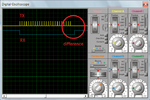
I dont have "a scope" to check my Tx frequency. But from the ISIS 7 simulator I saw that its
inbuilt scope also shows some time difference(could be 5KHz, please check the image 40Khz carries.png). But I made 40Khz carrier (As my receiver module is 40KHz please be noted I write wrong there), Please take a look at my calculation--


-------------------------------------------------------

Code C - [expand]
1
2
3
4
5
6
7
8
9
10
11
12
13
14
void pulseIR(unsigned int pulse)
{                                 //for 40khz IR modulation
  GPIO.GP5=0;
  while (pulse > 0)
  {
      GPIO.GP5=1;               
      Delay_us(5);              
      GPIO.GP5=0;               
      GPIO.GP5=0;               
      GPIO.GP5=0;               
      Delay_us(3);              
      pulse--;                  
   }
}


--------------------------------------------------------

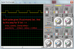
each pulse creat 25uS time duration(please check the image bit.png).
for 0-bit I calculate 600uS + 25x24uS = 1.2mS
for 1-bit I calculate 600uS + 25x48uS = 1.8mS
for start bit I calculate 600us + 25x96uS = 2.4mS

when I transmit signal It send/shows right time period(600uS) but the receiving time period always greater(it is 650uS, image 40Khz carries.png) than the transmitting time period. where my problem is?

40Khz carries.pngbit.png

During this blog creating, My problem was in the receiver module I found my problem; it was in Timer1 setting configuration. I fix it I attached the file named "tx12F675rx12F675.zip". Please checked it. But I still have some other problem.

My application is to ON/OFF some relays.When I individually pressed the each button, it toggles but when I try to 'ON' all LED by pressing the buttons It shows the error(image problem.png). Please Help to fix it.

problem.png
 

Attachments

  • tx12F675rx12F675.rar
    429 KB · Views: 173
Last edited by a moderator:

Ah... so you are using Sony protocol at 40KHz.

Now your code starts to make sense

Might I suggest that you put that information in your C code comments if you want others to understand your code. The Tx code still says 38KHz in comments

I is normal for the Receiver output to have mark signals stretched and space signals compressed. Your receiver code needs to handle a range of pulse widths to allow for this distortion, which varies according to distance.

I must go to work now, but I will look at your new code later.
 
  • Like
Reactions: bkar

    bkar

    Points: 2
    Helpful Answer Positive Rating
As hexreader points out, received pulse widths in IR may not be the same as the transmitted ones. Thus there is usually additional coding to account for that. One method is called Manchester coding.

Here are links to a series of tutorials by Nigel Goodwin.

Link to all tutorials: http://www.winpicprog.co.uk/pic_tutorial.htm
Link to tutorial on Manchester coding: http://www.winpicprog.co.uk/pic_tutorial12.htm
Link to Sony coding: http://www.winpicprog.co.uk/pic_tutorial5.htm

Those tutorials have been converted to C by Ian Rogers. I don't have the direct links handy to the C versions handy, but the descriptions above should help you in understanding the pulse width problem.

Edit: There is also a group here that has many useful links:
Edit2: Here is the link to the translated tutorials: http://www.electro-tech-online.com/content/467-nigel-goodwin-s-tutorials-c.html It looks like both #5 and #12 are completed (scroll to bottom of page).


John
 
Last edited:
  • Like
Reactions: bkar

    bkar

    Points: 2
    Helpful Answer Positive Rating
I have looked at your Tx code and it looks fairly close, but I suggest the following changes to get 40KHz, rather than 44 KHz, and to provide some comments (though still not enough).

Code:
// send 'pulse' cycles of 40 KHz at 25% duty cycle
void pulseIR(unsigned int pulse)
{                               // 40KHz IR modulation
  GPIO.GP5=0;                   // IR transmitter is on GP5
  while (pulse > 0)
  {
      GPIO.GP5=1;               //  .8 uS
      Delay_us(7);              //
      GPIO.GP5=0;               //  .8 us
      GPIO.GP5=0;               //  .8 us
      GPIO.GP5=0;               //  .8 us
      Delay_us(3);              //  3
      pulse--;                  ///13+ 5.6 As 5 instruction line(per line .2 uS)
   }
}

I would also add comment at the top of Tx code to say that you this is a Sony IR tx program using PIC12F675 and a whole load more useful information (like press button on GP0 to give address 01 and command 01) etc

Now I will check out your Rx code....
 

[/QUOTE]I would also add comment at the top of Tx code to say that you this is a Sony IR tx program using PIC12F675 and a whole load more useful information (like press button on GP0 to give address 01 and command 01) etc.

Now I will check out your Rx code....[/QUOTE]

Dear hexreader,
Thanks for your valuable comments. I've seen your CODE.
How you calculate that my ir carrier code provides 44Khz. And 25% duty cycle means what? Actually I've some lacks, (you could know!). I followed you suggestion(TX) I've seen form the ISIS 7's scope that a single pulse takes about 28uS time. Which will mismatch the receiver timing calculation. Now I am going to reconfigure both TX & RX. & I'll continue my writing, please help me..... .

I one more thing; do you see my last attachment? Though I don't following the principle, but 12F675 TX & RX are seems ok, except the WDT massage. Why?I could not understand Is there any way to disable that problem. Again thanks

Bahadur Kar
info.bkar@gmail.com
+8801684070724
 
Last edited:

How you calculate that my ir carrier code provides 44Khz.
I did not calculate it, I measured it with an oscilloscope.

And 25% duty cycle means what?
The IR LED will be lit for 25% of each 40KHz cycle, and off for 75% of each cycle.
Using 25% duty cycle saves battery power without reducing range significantly. Domestic IR remote protocols typically use 25% to 33% duty cycle, but anything 25% to 50% will be good.

Yes I saw your last attachment and will work with that.

What WDT message do you have? I had no message.

I am using real hardware only. I know nothing of ISIS 7.

I will start to look at your Rx code now

---------- Post added at 20:34 ---------- Previous post was at 20:19 ----------

Ok, I have had a look at your latest Rx code.

Again it is difficult to follow because the comments are poor.

First problem: Which pin of the PIC12F675 is the IR receiver connected to?
Code:
// GP2 interrupt set up
//******************************************************************************
     INTCON.INTE = 1;              //enable RB0 interrupt.
One comment seems to suggest GP2, the other suggests RBO
 
Last edited:

Dear hexreader,

Sorry for my mistaken. That is not RB0 Pin, that is GP2 default interrupt pin of 12F675.
I am checking my CODE again and upload that file. Again sorry !:-|

Is my code works on your hardware? ISIS 7 is software for simulation. When I run the project on that software It gives me a warning massage, which I add previous attachment. Please check the image name "problem.png". Though it gives a warning massage but it works.

Thanks
 

Dear hexreader,

I solved the problem. Thanks for you suggestion.

Thanks

Code:
unsigned counter = 0;
unsigned input_data, bit_count;

enum {
        Idle,
        Start_bit,
        Capture_bit
};

char Current_state = Idle;
char got_data = 0;
char Command_code, Device_code;

void interrupt(){
     if(INTCON.INTF){
        T1CON.TMR1ON =1;                          //timer1 On
        switch (Current_state){
           case Idle:
                      OPTION_REG.INTEDG = 1;    //interrupt on rising edge.
                      counter = 0;
                      Current_state = Start_bit;
                      break;
           //found the rising edge, check lenght for 2.4ms
           case Start_bit:
                      //correct signal, move on to next state
                      if(counter==4) {
                         counter = 0;
                         bit_count = 0;
                         input_data = 0;
                         Current_state = Capture_bit;
                         } else {
                            //fault signal, reset to Idle
                            Current_state = Idle;
                         }
                      break;
           case Capture_bit:
                      //check plus length for 0 or 1
                      if(counter==2){
                         input_data >>= 1;             // add 0 to received data
                         bit_count++;
                      }
                      else if(counter==3){
                            input_data >>= 1;
                            input_data |= 0x8000;     //add 1 to received data
                            bit_count++;
                         }
                      //complete 12 bit
                      if(bit_count >= 12){
                         got_data = 1;
                         input_data >>= 4;
                         OPTION_REG.INTEDG = 0;    //interrupt on falling edge.
                         Current_state = Idle;
                      }
                      counter = 0;
                      break;
            default: Current_state = Idle;
        }
     INTCON.INTF = 0;                       //clear interrupt flag.
     }
     if(PIR1.TMR1IF){
        counter++;
        TMR1H = 0xFF;                        //16bit timer1 register value High order(8bit)
        TMR1L = 0x6A;                        //16bit timer1 register value low order(8bit)
        if(counter > 5) {
            Current_state = Idle;
            counter = 0;
            OPTION_REG.INTEDG = 0;    //interrupt on falling edge
        }
        PIR1.TMR1IF = 0;                    //clear interrupt flag
      }
}
//******************************************************************************
// MAIN  MAIN  MAIN MAIN
//******************************************************************************
void main() {
     TRISIO = 0b00001100;            //Configure I/O Pin
     GPIO = 0x00;                          //Set all output to 0
     ANSEL = 0;                             //All digital I/O
     CMCON = 7;                           //Disable Comparator
//******************************************************************************
// GP2/INTE interrupt set up
//******************************************************************************
     INTCON.INTE = 1;                  //enable GP2/INT interrupt.
     OPTION_REG.INTEDG = 0;       //interrupt on falling edge.
//******************************************************************************
// Timer1 interrupt setting, interrupt every 600us  timer register value TMR1H = 0xFF; TMR1L = 0x6A;
// Clock source Internal Oscillator 4Mhz
//******************************************************************************
     T1CON.T1CKPS1 = 1;              //prescaler 1:4
     T1CON.T1CKPS0 =0;
     PIE1.TMR1IE = 1;                    //enable timer1 interrupt
//******************************************************************************
// Global interrupt enable
//******************************************************************************
     INTCON.PEIE = 1;                    //enable interrupt
     INTCON.GIE = 1;                     //enable global interrupt

while(1){
              if(got_data){
              Command_code = input_data & 0x7F;
              Device_code = input_data >> 7;
              got_data = 0;
                if(Device_code == 1){
                   switch (Command_code){
                      case 1: GPIO.GP0 = ~GPIO.GP0;  break;
                      case 2: GPIO.GP1 = ~GPIO.GP1;  break;
                      case 3: GPIO.GP4 = ~GPIO.GP4;  break;
                      case 4: GPIO.GP5 = ~GPIO.GP5;  break;
                  }
               }
            }
          asm clrWDT;
          }

}
 
Last edited:
I have looked at your Tx code and it looks fairly close, but I suggest the following changes to get 40KHz, rather than 44 KHz, and to provide some comments (though still not enough).

Code:
// send 'pulse' cycles of 40 KHz at 25% duty cycle
void pulseIR(unsigned int pulse)
{                               // 40KHz IR modulation
  GPIO.GP5=0;                   // IR transmitter is on GP5
  while (pulse > 0)
  {
      GPIO.GP5=1;               //  .8 uS
      Delay_us(7);              //
      GPIO.GP5=0;               //  .8 us
      GPIO.GP5=0;               //  .8 us
      GPIO.GP5=0;               //  .8 us
      Delay_us(3);              //  3
      pulse--;                  ///13+ 5.6 As 5 instruction line(per line .2 uS)
   }
}

I would also add comment at the top of Tx code to say that you this is a Sony IR tx program using PIC12F675 and a whole load more useful information (like press button on GP0 to give address 01 and command 01) etc

Now I will check out your Rx code....


Hi,

I was looking at this code and wanted to know how did you arrive at 40 KHz carrier frequency ?
Is it like ( 20MHz crystal -> 5MHz clock -> 1.25MHz / instruction -> 0.8us per instruction ?
How did you make calculations to get 25us ( 1/40KHz) ?
Can you please explain ? sorry for the late post.
 

Already answered in post #8.

I did not calculate anything, I measured using an oscilloscope.
Oscilloscope ok, but how did you know how much delay to put so that you can match the time period for the corresponding frequency ?
Was it hit and trial or is it that the delay that you have introduced does not even play a role in deciding the time period ?
Thank you
 

.... hit and trial .....

You cannot reliably and accurately calculate how long any particular line of C code will take to execute, though it looks as though the OP tried to (but failed)

If the code had been written in assembly language, then the time to execute an assembly instruction could be calculated.

Is there any reason as to why PWM was not used ?
 

This PIC has no hardware PWM module if I remember correctly.

Check the datasheet to be sure.
 

Status
Not open for further replies.

Part and Inventory Search

Welcome to EDABoard.com

Sponsor

Back
Top