Continue to Site

Welcome to EDAboard.com

Welcome to our site! EDAboard.com is an international Electronics Discussion Forum focused on EDA software, circuits, schematics, books, theory, papers, asic, pld, 8051, DSP, Network, RF, Analog Design, PCB, Service Manuals... and a whole lot more! To participate you need to register. Registration is free. Click here to register now.

Help me with voltmeter code for PIC16f876

Status
Not open for further replies.

birlan97

Junior Member level 3
Joined
Feb 28, 2010
Messages
29
Helped
0
Reputation
0
Reaction score
0
Trophy points
1,281
Location
romania
Activity points
1,502
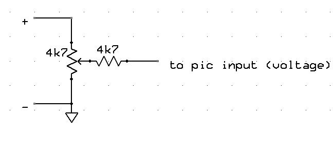
I have some problems with this voltmeter (value reading are not stable and are not linear).

I configured resistive divisor at imput 1 (AN0) to match lower limit voltage, but when I rise the voltage to be measured, the pic reading is lower than real voltage) and is not stable.
Could anubody help me ?

this is the code:

#include <16F876.h>
#device ADC=10
#fuses HS,NOWDT,NOPROTECT,NOLVP
#use delay(clock=20000000)
#include <flex_lcd.c>

unsigned long value,volts,amps;
float volts_read,amps_read;

void main() {

setup_port_a( ALL_ANALOG );
setup_adc( ADC_CLOCK_INTERNAL );
delay_ms(10);
value = 0;
volts = 0;
amps = 0;

lcd_init();
printf(lcd_putc,"\f");
printf(lcd_putc," Volts Amps \n");


do {
set_adc_channel( 0 );
volts = Read_ADC();
set_adc_channel( 1 );
amps = Read_ADC();
volts_read = (float)(volts * 23.5)/1023;
amps_read = (float)(amps * 3)/1023;
lcd_gotoxy(2,3);
printf(lcd_putc," %2.2f %2.2f ",volts_read,amps_read);
delay_ms(100);

} while (TRUE);
}
 

Re: pic16f876 voltmeter

Hi,

You could add a 100 nF cap on each analog pin input for a more stable reading ...

What is the error @ the high end of the measure range ?
 

pic16f876 voltmeter

are u reading ac volt(rectified ) or dc volt if dc adding a 100nf cap will be fine. if ac you have to do more filter cap or by taking average value of adc

post the circuit for detail
 

Re: pic16f876 voltmeter

The 100nF caps helps, but still need more stability
Voltage reading seems to be OK (no less no more than a regular multimeter reading). First measurement which I made appear to be lower than real voltage because of instability, now with 100nF caps is better, but after decimal point is a mess. I have not implemented the circuit divisor for Amps reading, just added 100nF cap to the ground. I observed when I rise the voltage , the current rise too with the Amps imput not connected .If I put the Amps input to the GND or to 100nF to GND the voltage reading drops to more than a half (example: I have to measure 20v when I connect Amps imput to the GND the voltage show 8.35v)
What should I do to resolve the problems ?
Tks you all !
 

Re: pic16f876 voltmeter

I'm reading regulated switching supply voltage
 

pic16f876 voltmeter

you can make it more stable by adding 1uf or more capacitors or by reading 10 or 20 adc values and taking average of it
 
  • Like
Reactions: pnjbtr

    pnjbtr

    Points: 2
    Helpful Answer Positive Rating
Re: pic16f876 voltmeter

How do I read 2 different channels (A0 and A1) and store in different variables ?
It is correct this code ?

-----------------------------------------
set_adc_channel( 0 ); //set input A0 - voltage
volts = Read_ADC();
set_adc_channel( 1 ); //set input A1 - amps
amps = Read_ADC();

-----------------------------------------

I asked because when I change level of one input , is changing the other one too
https://www.youtube.com/watch?v=xsgC4_OLiG4
 

Re: pic16f876 voltmeter

If changing the voltage on one input changes the reading on the other, either you have an electrical connection between them (unlikely) or you are not leaving long enough after changing channel for the ADC to settle (most likely).

Try introducing a delay after selecting the channel and taking the reading. There are guidelines in the data sheet on how to do this.

Remember that the IC only has one ADC unit, it's the inputs to it that are changed. If the input changes and you try to read the voltage straight away, some of the charge from the previous reading will still be present.

Brian.
 

Re: pic16f876 voltmeter

You are right
introducing a delay after selecting channel solve the problem
Thank you
 

pic16f876 voltmeter

int i=0;
.
.
.


for (i=0;i<=10;i++)
{
delay_ms(1);
volts = volts+Read_ADC();
}
set_adc_channel( 1 );
for (i=0;i<=10;i++)
{
delay_ms(1);
amps = amps+Read_ADC();
}
volt=volt/10;
amps=amps/10;


you can do the loop for more times and take the average for better value, the delay can be reduced less than 100us
 

Re: pic16f876 voltmeter

birlan97
Tell me you LCD set and I will send you some code to try, The hardwre look ok to me.
I know your using port be but the drawing does not state the pins.
 
Re: pic16f876 voltmeter

LCD setup:

....................................
#define LCD_DB4 PIN_B4
#define LCD_DB5 PIN_B5
#define LCD_DB6 PIN_B6
#define LCD_DB7 PIN_B7

#define LCD_RS PIN_B2
//#define LCD_RW PIN_B5 - connected to the ground
#define LCD_E PIN_B3

// If you only want a 6-pin interface to your LCD, then
// connect the R/W pin on the LCD to ground, and comment
// out the following line.

//#define USE_LCD_RW 1
....................................
 

Re: pic16f876 voltmeter

birlan97

Try this, I know the readings may not be spot on comparing your meter against it, This can be calibrated later on. but see if the readings remain stable enough, You may get a little but nothing that should casue any concern.
PORTRA.0 = Volt input 0-5V = 0-20.44Volts
PORTRA.1 = Amp input 0-5V = 0-10amps.

I'm not sure how your reading the amps or how high, If it works and need to calibrate the voltage set your source input half way and measure the voltage at the pic and let me know,
Let me know how you get on
 

Re: pic16f876 voltmeter

Sorry I made a mistake with that one, I still left it set for 877 and not 876

so try this one
 

Re: pic16f876 voltmeter

OK, something else to check...

Before measuring the voltage, the input multiplexer has to charge a capacitor inside the PIC. The rate of charge depends on how much current you allow into to the input pin. In your schematic you use 100KΩ resistor in a potential divider, these values are far too high and the pin current will be seriously restricting the charge rate.

Microchip recommend you do not exceed 10KΩ input impedance. Lower values work better. I suggest you scale down the resistors around the input pin so they are much lower. If this causes a problem by loading the voltage you are trying to measure, the only option open to you is to use an amplifier to convert high to low impedance.

Brian.


Re: pic16f876 voltmeter

Mine does not do that on my baord. This is one of the ways that I do mine, You might have to paly around with the values because I only needed to measure up to 8V olt max.

The second one is another way ths goes up to 50 volts using an op-amp has a buffer
 

Re: pic16f876 voltmeter

I modified the input scheme for the voltage with your divisor scheme (ad imput.bmp) snd is the same result.
wizpic your hex is taken more reading and make an average to display ?
If not the next thing I'll try is rajudp ideea and if this wouldn't work too, the ideea with operational amplifier is too complicated to me ( I do not know much electronics to calculate the scheme)

Added after 11 minutes:

By the way, how do I measure amps ? I've connected in series with ground output a 0.1ohm resistor , and I measured voltage dropout on it, but the voltage was very low. How can I calibrate the amps reading ?
Here is the code:
----------------------------------
set_adc_channel( 0 );
delay_ms(50);
volts = Read_ADC();
set_adc_channel( 1 );
delay_ms(50);
amps = Read_ADC();
volts_read = (float)(volts * 22)/1023;
amps_read = (float)(amps * 51)/1023;
amps_val = (float)amps;
lcd_gotoxy(2,2);
printf(lcd_putc,"%2.2f",volts_read);
lcd_gotoxy(12,2);
printf(lcd_putc,"%2.2f",amps_read);
delay_ms(10);
----------------------------------

volts_read = (float)(volts * 22)/1023; //22 is my max voltage output

amps_read = (float)(amps * 51)/1023 //3 is my max current output
here it must be 3 instead 51 but with 3 the amps reading is very low

It's that correct ?
 

Re: pic16f876 voltmeter

To boost the voltage for the current you need an op-amp set has a gain amplifier, So you draw 2.5Amps (not sure what the MV reading would be) say if it was 33MV acrross the resitor then the op-amp would boost the voltge to 2.5v say then the pic can read this.
Has for the voltage not been stable
Q1. How is the PCB laid out (sounds like a niose problem to me)
Q2. Have you got some 100NF decoupling caps in the 5V line ad one right by the pic
Q3. have you got some smothing caps accross the 5V supply
Q4. How are you tapping in to the power supply to measure the voltage aslo is the voltag going into the PIC stable

I tried it on my easy pic board and it only goes up/down by .01V and that's the best your going to get it.
The PDf version with the op-amp you can just use a LM358(not the best though) or any other single or daul op-amp instead of the quad one. so simple when you understand it.
I take 63 samples then work out an average

wizpic
 

Status
Not open for further replies.

Part and Inventory Search

Welcome to EDABoard.com

Sponsor

Back
Top