NTFS
Member level 3
Hi all
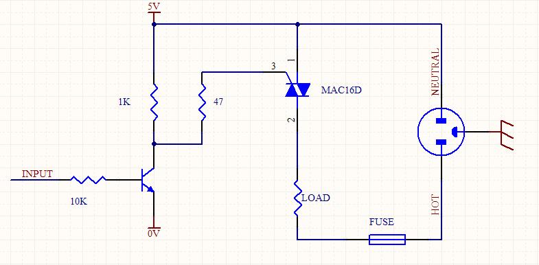
I made this circuit to be a light dimmer but it did not work. I use BT136 for the SCR and MOC3022 for optocoupler.
Can you tell me what is the problem? may be I should use another SCR.
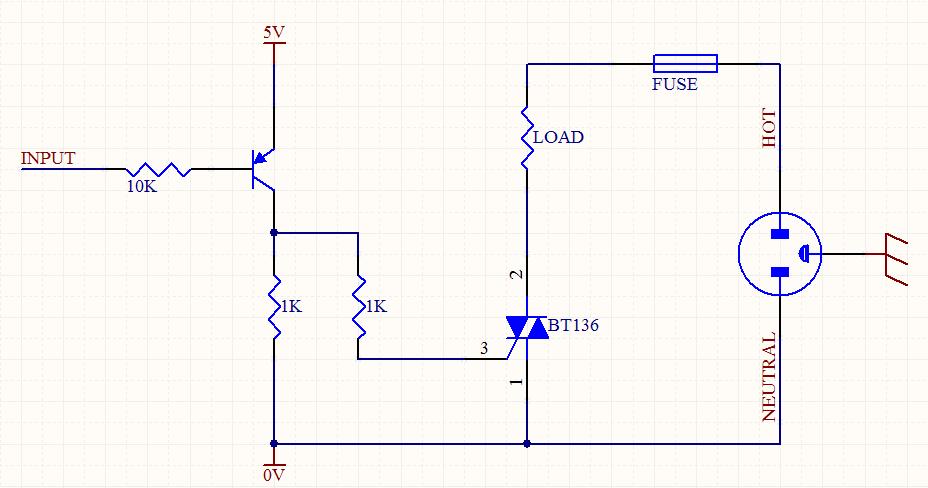
I made this circuit to be a light dimmer but it did not work. I use BT136 for the SCR and MOC3022 for optocoupler.
Can you tell me what is the problem? may be I should use another SCR.