copilu
Newbie level 4
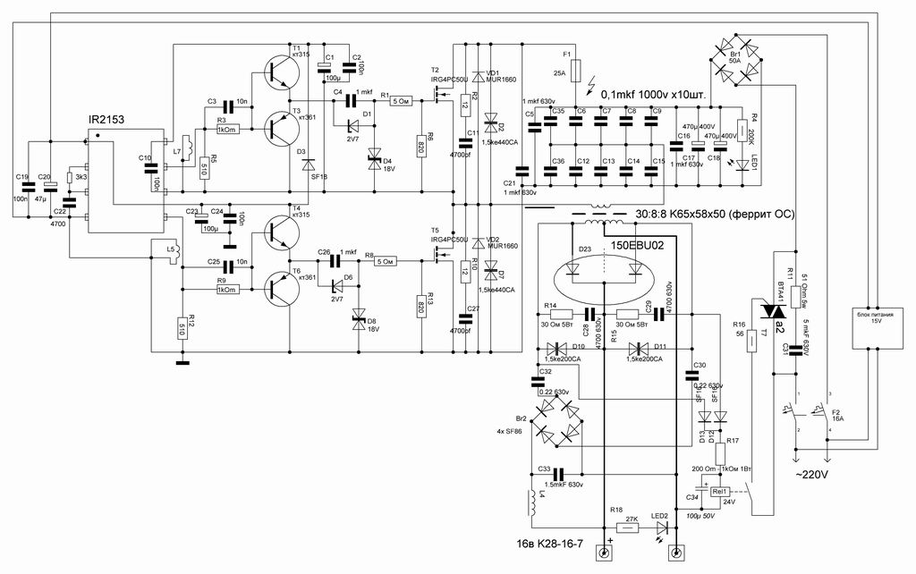
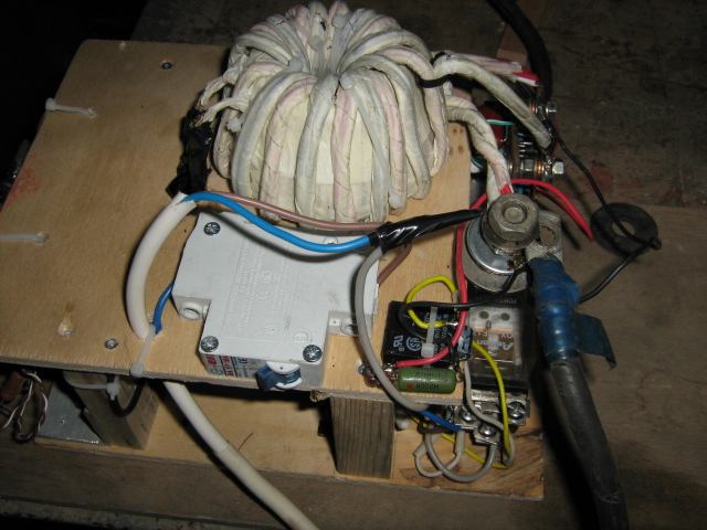
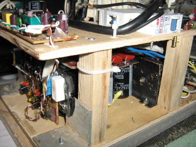
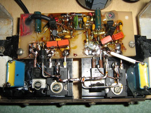
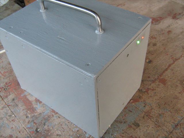
welder schematics
i really don`n know. i have the document "as it is"
ibersoy2006 said:i need switdh mode arc welder machine use microcontroller type number and datasheet
Added after 4 minutes:
i need to invertor sudura.pdf of the use microcontroller type number it did not write shematic diagram you give microcontoller type number i be very happy
thanks
i really don`n know. i have the document "as it is"