Continue to Site

Welcome to EDAboard.com

Welcome to our site! EDAboard.com is an international Electronics Discussion Forum focused on EDA software, circuits, schematics, books, theory, papers, asic, pld, 8051, DSP, Network, RF, Analog Design, PCB, Service Manuals... and a whole lot more! To participate you need to register. Registration is free. Click here to register now.

Short circuits 3, project 22, 3 stage FM transmitter

Status
Not open for further replies.

boylesg

Advanced Member level 4
Joined
Jul 15, 2012
Messages
1,023
Helped
5
Reputation
10
Reaction score
6
Trophy points
1,318
Location
Epping, Victoria, Australia
Activity points
11,697
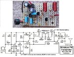
I have got this project working brilliantly with an FM radio - impressed.

View attachment 146201

But I have run into a problem and learned something new about electret microphones in the process.

I bought a mono shirt collar microphone to use with it in place of the supplied electret that is normally soldered straight on to the PCB - more convenient for practical use in the scenario I have in mind.

But the audio coming through on the radio is very weak when I use the chorded microphone, but very strong if I use the supplied electret plugged straight onto the headers I have put on the PCB.

I assume that to much power is being lost over the long lead since the amount of current with a 47k resistor (that powers the electret) is tiny anyway.

So would it be as simple as replacing that 47k resistor with a 10k or less resistor?

Or is it more complicated than this?
 

The lead length has nothing to do with it although intuitively 47K is too high, I would use about 22K (microphone current ~ 0.5mA) myself. Are you sure the replacement microphone is an electret type and it is wired the right way around? Electrets generally have a much higher signal output than dynamic or a loaded crystal type.

(clue: measure the DC resistance across the microphone wires, >1M is a crystal type, ~200 Ohms to 1K is probably dynamic, different resistances in each direction is probably electret)

Brian.
 

There is a sticker on the electret inside that says 10k 16.

10k ohm at 16V?

The electret that came with the kit has a resistance of about 1.1k one way and about 980r the other way.
The electret that is in the corded microphone has a resistance of about 2.2k one way and about 1.9k the other way.

I guess I could remove the electret that came with the microphone and replace it with the electret that came with the kit.

One thing I have noticed about this FM kits is that they are damn hard to tune in to a particular frequency because your hand in close proximity to the circuit or a screw driver touching the trim cap changes the transmission frequency slightly.

And you have to turn the trim cap by minute amounts - very difficult.
 
Last edited:

Your attachment does not work.
Without seeing the schematic I am guessing that the 47k resistor powering the electret mic is connected to 6VDC. Then with a mic current of 0.5mA the voltage across the 47k resistor is 47k x 0.5mA= 23.5V which means the mic has no voltage and will do nothing.
The value of the resistor is selected to produce 2VDC to 5VDC across the mic. With a 5V supply the mic will have 2.5V across it when the resistor value is (5V - 2.5V)/0.5mA= 5k ohms.
With the circuit powered, measure the voltage across the mic. It should be 2VDC to 5VDC.

Maybe the schematic or parts list is difficult to read and the 47k resistor is actually 4.7k?

Well the attached schematic is from the kit and it works brilliantly....with the electret microphone supplied with the kit and with it attached directly to the PCB.

But my aim is to make it work as well with the corded electret microphone I bought in addition to the kit.

Either by changing out some resistors or by swapping the electret microphone in the corded microphone I bought.

But there is no use doing anything until I understand the difference between the kit supplied electret and the chorded microphone - why the former works well and the other not so well.
 

...hard to tune in to a particular frequency because your hand in close proximity to the circuit or a screw driver touching the trim cap changes the transmission frequency slightly.

And you have to turn the trim cap by minute amounts - very difficult.

I purchased a kit of plastic tools for adjusting trimmers of various types. They do not cause frequency shifts. Hex wrenches for inductors. Screwdrivers for pots and capacitors.
 

I purchased a kit of plastic tools for adjusting trimmers of various types. They do not cause frequency shifts. Hex wrenches for inductors. Screwdrivers for pots and capacitors.

I don't suppose coating metal ones with a thin film of plastic would make much difference?
 

I don't suppose coating metal ones with a thin film of plastic would make much difference?
Very little. It's the capacitance of the tool and your body when connected to the tuned circuit that shifts the frequency. A plastic tool is best but there are some things you can do to make it more stable:

1. put L1, the 10pF capacitor and the trimmer inside a screened can (the whole oscillator would be better), ground it but obviously leave a hole to make adjustments.
2. make sure the screw slot of the trimmer is connected to the +9V rail. It works equally both ways around but the adjuster is usually connected to one of the pins and touching the transistor end will shift the frequency more than the supply end.

I suspect your "10K 16" is a model or batch code with the "16" probably meaning it was manufactured in 2016. My guess is it isn't an electret though. They cost pennies so I advise you buy a new electret and use that.

Brian.

What else would it be then? It looks exactly like an electret microphone with the metal can and the solder contacts.
At any rate I removed the microphone and replaced it with the electret that came with the kit.
There was also a problem with the way I had it connected to the PCB.

I.E. Header female to a small piece of matrix board with a stereo audio socket. Don't know what was wrong with this.

I just ditched it, cut the mono audio plug off the corded microphone, replaced it with a female header connector and the corded microphone now plugs directly onto the PCB.
It works brilliantly now with the corded microphone.
 

When I said your attachment does not work I did not say your circuit does not work. Instead I do not see the schematic, instead I see this:
 

Attachments

  • attachment does not work..png
    attachment does not work..png
    3.9 KB · Views: 150

When I said your attachment does not work I did not say your circuit does not work. Instead I do not see the schematic, instead I see this:

Oh!

How this then?

FMTransmitter.jpg

In fact it works so well now, with the mono audio plug removed and the corded microphone containing the electret that came with the kit, that with the microphone on the ground about 1.5-2.0m from the tv I can hear the tv clearly on my mobile phone (through the fm radio app) from the back of the house.

I am truly impressed. I would love to build up enough knowledge to design such analog circuits from scratch.
 

Doesn't that FM transmitter produce muffled high audio frequencies? It is because it is missing pre-emphasis (high audio frequencies boost) that all FM radio stations have and all FM radios have the opposite de-emphasis that cuts the boosted highs down to normal and cuts hiss.
My FM transmitter has pre-emphasis calculated for the different amounts in the world so it sounds perfect. My circuit uses R5 and C4 to do it. C2 prevents the audio preamp from amplifying the radio frequency.
 

Attachments

  • FM tx mod4 pic and schematic.jpg
    FM tx mod4 pic and schematic.jpg
    196 KB · Views: 163

Doesn't that FM transmitter produce muffled high audio frequencies? It is because it is missing pre-emphasis (high audio frequencies boost) that all FM radio stations have and all FM radios have the opposite de-emphasis that cuts the boosted highs down to normal and cuts hiss.
My FM transmitter has pre-emphasis calculated for the different amounts in the world so it sounds perfect. My circuit uses R5 and C4 to do it. C2 prevents the audio preamp from amplifying the radio frequency.

The sound quality coming from my mobile phone seems quite good to me Audio.

Perhaps if you analysed it with an oscilloscope you might find deficiencies.

The aim is for Mum to hear Dad calling from another room or from the village centre, and the kit is certainly good enough for that.

Why are there two tank circuits in your schematic?
 
Last edited:

FM radio is supposed to have high fidelity with a bandwidth from 50Hz to 15kHz. The de-emphasis in all FM radios cuts high frequencies about the same as your stereo with its treble tone control turned down all the way. Obviously muffled.

The first LC in my FM transmitter is the oscillator. If the antenna is connected to it then the radio frequency changes if something moves towards or moves away from the antenna due to added or decreased capacitance.
The second LC is broadly tuned and its transistor isolates the antenna from the oscillator.
 

Status
Not open for further replies.

Part and Inventory Search

Welcome to EDABoard.com

Sponsor

Back
Top