Continue to Site

Welcome to EDAboard.com

Welcome to our site! EDAboard.com is an international Electronics Discussion Forum focused on EDA software, circuits, schematics, books, theory, papers, asic, pld, 8051, DSP, Network, RF, Analog Design, PCB, Service Manuals... and a whole lot more! To participate you need to register. Registration is free. Click here to register now.

DIY smart phone cradle antenna

Status
Not open for further replies.

yotam

Newbie level 2
Joined
Apr 20, 2018
Messages
2
Helped
0
Reputation
0
Reaction score
0
Trophy points
1
Activity points
24
My office is located below the ground level and therefore GSM reception is not satisfying so I am using a simple 4G Antenna placed outside where the signals are strong enough.

The antenna wire is on my desk and I keep the phone close to it. Simple, but it works, I can get my SMS instantly without having to go up with the phone.

I would like to build a cradle and connect the SNA connector to a PCB which most of it would be a copper plate that will be located underneath the phone.
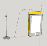
7ucGt.png

My question is how to design the copper plate, should it be grounded, and how, should it be spiral or flat? any other considerations?

Here's several inner antenna designs, remember that the phone back side would be flat with the antenna PCB. Which of the designs, if any, makes sense for this particular need?

antenna.png

Thanks!
 

None of it. A dual band patch antenna with 50 ohm matching.

I would like to make an antenna from a PCB lying under the phone, what would be the best layout?
 

My best guess is that in the near field, electric field coupling (open ended structures) works better than closed loop magnetic coupling, because the phones internal antennas are usually PIFA-style.

In any case, such large metal lying directly under the phone would detune the internal phone antenna a lot. The phone antenna isn't designed to operate directly above large metal planes.
 

Passive mobile phone antenna couplers are widely available as retail products, build into modern cars and also made as measurement and test accessory, e.g. from R&S. Just google it.

For sure a nearby structure will modify the embedded antenna characteristic. With a good coupling factor, it must not necessarily detune it too much. Apparently the existing solutions don't, said to have only a few dB loss.
 

Hi Frank,

interesting!

You are right that there is a need for such devices. Having worked on antenna designs, I just wonder what is an efficient universal way to couple an antenna (designed for far field radiation) to a near field device.

Some of the cheap retail stuff is specified with "at least 6-9db" coupling losses, so I wonder if you have data on the R&S device, or any insight how they implemented this?

Best regards
Volker
 

Status
Not open for further replies.

Part and Inventory Search

Welcome to EDABoard.com

Sponsor

Back
Top