Continue to Site

Welcome to EDAboard.com

Welcome to our site! EDAboard.com is an international Electronics Discussion Forum focused on EDA software, circuits, schematics, books, theory, papers, asic, pld, 8051, DSP, Network, RF, Analog Design, PCB, Service Manuals... and a whole lot more! To participate you need to register. Registration is free. Click here to register now.

[SOLVED] What is the best software to simulate a boost converter with current control?

Status
Not open for further replies.
Re: what are the best software to simulate a boost converter with current control ?

I fail to recognize how the said "vout/verr" transfer function is different from the loop gain already derived at the start of this thread, but evaluated for a different loop, the outer voltage control.

A possible trap door in case of the discussed converter is that the loop gain partly varies with the operation point, particularly in DCM. Thus it's suggested to operate the system in feedback with a useful set point.
 

Re: what are the best software to simulate a boost converter with current control ?

I fail to recognize how the said "vout/verr" transfer function is different from the loop gain already derived at the start of this thread, but evaluated for a different loop, the outer voltage control.
Yes, I understood the same as you until he showed the formula he is using in post #17.

In post #17, "vout(s)/verr(s)" is not the loop gain. Why ? Because I see no compensator transfer function involved. Besides, why would an author give a "general" expression using a specific type of compensator ? Everyone will use that compensator ? It does not make sense.

Like I said, the name "vout/verr" is misleading because they are using "verr". So, I simply took it as the control-to-ouput transfer function (Gvc(s)=vout(s)/vc(s), I think what I call "control Vc", you call it "set point ramp").

The setup is as below.

Gvc(s)-setup.png
 
Re: what are the best software to simulate a boost converter with current control ?

The Plecs schematics in post #15 and #17 have a PI voltage controller, respectively vout/verr reflects it's gain multiplied with the vout/iref transfer function of the underlying loop. I'm referring to the verr specification in the #15 schematic and didn't check if the equations are consistent with this schematic. If not, I presume erroneous equations.

Your "control-to-ouput transfer function" (vout/iref ) is the voltage control loop gain with the PI gain set to constant 1.

I also notice that post #15 continuous the confusion already mentioned in post #4. The perturbation as well as the vout/verr measurement are already included in the Plecs loop gain meter.
 

Re: what are the best software to simulate a boost converter with current control ?

Your "control-to-ouput transfer function" (vout/iref ) is the voltage control loop gain with the PI gain set to constant 1.
I agree, theoretically, but not in PLECS. Do that in PLECS and see that it displays nothing. :grin: You must do it as I did in order to get the result.

Regarding your original question: Why "vout/verr" is different than the loop gain showed in post #4 ?
Look the description in PLECS of "Small Signal Perturbation" and the "Small Signal Gain". They are different.

Small Signal Perturbation --> just adds a perturbation. In post #15, adding the perturbation to the error, is the same as adding the perturbation to the "Vref" signal, like asdf said. Then, computing vout/verr with the "Small Signal Perturbation" block, effectivley calculates Vout/Vref = T(s)/(1+T(s)) i.e. closed loop transfer function.

Small Signal Gain (right click -> subsystem -> look under mask) --> Look how it is being measured. They are measuring between the 2 terminals of the "Small Signal Gain" block, effectively giving the loop gain (NOT Vout/perturbation Block, as it was with the above), just as Middlebrook's injection method.
 
Last edited:

Re: what are the best software to simulate a boost converter with current control ?

I'm still not clear on what tarikelec wants to see. Is it truly the open loop response of the voltage loop that's wrapping the inner current loop? I'd like to see a bode plot picture of what tarikelec wants to see from the book.

The inner peak mode current loop is going to be quite an effective voltage-to-current converter up until the switching frequency. So everything from the peak current mode block and after (including all the switches) can be well approximated by a voltage controlled current source leaving quite a simple transfer function with the main variables being the V-to-I gain of that current source, the output C and the load.
 

Re: what are the best software to simulate a boost converter with current control ?

I agree, theoretically, but not in PLECS. Do that in PLECS and see that it displays nothing. You must do it as I did in order to get the result.

Regarding your original question: Why "vout/verr" is different than the loop gain showed in post #4 ?
Look the description in PLECS of "Small Signal Perturbation" and the "Small Signal Gain". They are different.

May be I don't get the objective of the discussion. I know how to measure loop gain, both for the inner current control as well as the outer voltage control loop. Using Middlebrooks method respectively the Plecs loop gain meter. Of course you can also determine close loop gain, e.g. for the voltage set point, but that's apparently not intended. So as far as I see, no other setups than the classical loop gain measurement are required.

Perturbation is as far as I see the required method to determine an equivalent time continuous gain of a discontinuous system, e.g. a switch mode controller. Not sure with other difference you are referring to.
 

Re: what are the best software to simulate a boost converter with current control ?

So as far as I see, no other setups than the classical loop gain measurement are required.
How do you measure the control-to-output transfer function with the loop gain setup ? By setting PI gain to "1", I have no results (blank Bode plot).

Not sure with other difference you are referring to.
Differences in the measurement method, not the perturbation.
 

Re: what are the best software to simulate a boost converter with current control ?

hello cataM, FvM,asdf44,
whati want to get is exactly the same bode plot fo the boost converter transfer function in peak current mode control as you can see in my circuit, sorry i have showed you you only the CCM transfer function, there is as well the DCM transfer function which shows as well a DC gain differeb from 0.
so what i was trying to do is to have peak current control of the bost converter which i made in PLECS, in christophe basse where he derived his equations for the Vout(s)/Verr(s) that i Have implemeted in matlab and the code is below:
Code:
/%% the Data: value of the Boost converter´s element
%% christophe basso 225
Vin=20; % voltage input
Vout=40; % voltage output
r_cf=0.1 ;     %Output capacitor ESR
r_lf =0.1 ;    %inductr ESR
R= 200;       %Load resistor
C= 10.7e-6;         %Output Capacitor
L= 20e-6;          %inductor
M= Vout/Vin;          %conversion ration Vout/Vin
D=1-1/M;          %on duty cycle
D_=1-D;           %Off duty cycle, also denoted by 1 – D, depending on the mood
Fsw=2.2e6;        % switching  frequency
Tsw=1/Fsw;        %Switching period
Ri=1;         %sense resistor in current mode
S1=Vin/L;         %(S_1)inductor on slope, Vin/L for a boost converter
S2=(Vout-Vin)/L;         %inductor off slope, (Vout-Vin)/L
Sa=0.5*S2;         %external ramp compensation slope
mc=1+Sa/S1;         %compensation ramp according to ridley notation [2]:mc=1+Se/Sn;
%%
%%%%%%%%%%%%%%%%%%%%%%%%%%%%%%%%%%%%%%%%%%%%%%%%%%%%%%%%%%%%%%%%%%%%%%%%%%%%%%%%%%%
%% it must under a condition to awitch between the DCM and CCM if Icrit>IL or k_crit
%%Current mode, CCM(reference equations 1):
k=(R/(2*Ri))*(Vin/Vout); %% DC gain
b=(((1+(Sa/S1))*D_)-0.5)/Fsw;
a=1/((pi*Fsw)^2);
w_z1=1/(r_cf*C);
w_z2=(R*(D_^2))/L; % Righ half plane zero
w_p1=2/(R*C);

%G(s)=Vout(s)/Verr(s)
%G1
G1=tf(k*[1/w_z1 1], [1/w_p1 1]);
%G2
G2=tf([-1/w_z2 1],[a b 1]);

G_ccm=G1*G2;
bode(G1,{10,1e7});
bode(G2,{10,1e7});
options = bodeoptions;
options.FreqUnits = 'Hz'; % or 'rad/second', 'rpm', etc.
bode(G_ccm,options,{10,1e7})
grid on
%%
%%Vout(s)/Vin(s)
gain=Vout/(2*Vin);
G_in_o=tf(gain*[1/w_z1 1],[1/w_p1 1]);
bode(G_in_o,{10,1e7})
grid on
%%
%%%%%%%%%%%%%%%%%%%%%%%%%%%%%%%%%%%%%%%%%%%%%%%%%%%%%%%%%%%%%%%%%%%%%%%%%%%%%%%%%%%%%
%%current mode, DCM (reference equations 1)
tau=L/(R*Tsw);
M=1+sqrt(1+(2*(D^2))/tau)/2;
Fm=1/(S1*mc*Tsw);
Hd= ((2*Vout)/D)*(M-1)/(2*M-1);

w_z1d=1/(r_cf*C);
w_z2d= R/((M^2)*L);
w_p1d=(2*M-1)/((M-1)*(R*C));
w_p2d=2*Fsw*((1-(1/M))/D)^2;
G1d=tf(Fm*Hd*[1/w_z1d 1],[1/w_p1d 1]);
G2d=tf([-1/w_z2d 1],[1/w_p2d 1]);
G_dcm=G1d*G2d;

options = bodeoptions;
options.FreqUnits = 'Hz'; % or 'rad/second', 'rpm', etc.
bode(G_dcm,options,{10,1e7})
grid on

%%

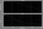
if i run just the CCM mode I get a bode plot like:

currentccm.png

with the cricuit shown in figurefor buck converter but mine is for boost instead.
as ou can notice there is DC gain of 34 dB which I wanted to obtain using the PLCS analysis tools (I have used as well the plecs blockset and got same problem), you were right placing the perturbaation after the (/*-) block leads to the transfer funcion Vout(s)/Vref(s)

- - - Updated - - -

I have found out as well that in chrstophe basso circuit when he derived the transfer function he did not include the PI conctroler so I did now but i get a blank bode plot as well
 

Attachments

  • iCONTOLNOPI.zip
    3.1 KB · Views: 91

Re: what are the best software to simulate a boost converter with current control ?

I don't really understand what's the purpose of operating the CM converter without PI controller for the voltage loop. But anyway it's possible, although involving a stationary voltage error as any pure P controller.

Problem with Plecs loop gain meter is apparently caused by unsuitable parameters and the initial transient. I had expected that "Simulation start time" option could be used to skip the initial transient, but it doesn't work at first sight. Initial condition for the output filter capacitor however does.

I think this answers also the previous discussion about different gain measurement methods. Of course the method used by CataM in post #22 works as well.

NoPI mod.PNG
 

Attachments

  • IcontrolBoost NoPI mod.zip
    2.9 KB · Views: 135
Re: what are the best software to simulate a boost converter with current control ?

cataN, in #22 you have used Vc as Verr and calculated it as 0.438 and took it from the closed loop . can you please tell how did you arrive to such value?
FvM. in the circuit you have used the loop gain Meter which is taken as input from the Vout and output it as feedback then get substracted from Vref to get the Verr which I fail to understand how can this be the Vout/Verr and your method gives almost (with more 6 dB, which i will look after this) the response as in the theory. here an example from their demos but they are saying it is in open loop gain and thansk again for the clarification

openlooporclosed.JPG
 

Re: what are the best software to simulate a boost converter with current control ?

cataN, in #22 you have used Vc as Verr and calculated it as 0.438 and took it from the closed loop . can you please tell how did you arrive to such value?
I simulated the circuit provided in post #1 and took the value "Iref" had in steady state.
 
Re: What are the best software to simulate a boost converter with current control ?

As said the #22 and #29 setup are expected to give the same gain curve for the same operation point. I did the loop gain meter setup basically to show that it can work, although Plecs has some problems to use the correct steady state solution, in so far the #22 open loop setup is probably less prone to faults.
 
Re: What are the best software to simulate a boost converter with current control ?

cataM, thank you so much, I got it now. but why on earth it does not give the same result (with DC gain) like in the first circuit as it seems as you have showed without the voltage feedback but just with Iref calculated after the block+/-?. I mean the Iref is the same as when you used directly the constant Iref (value you got from teh steady state) and when I use the voltage feedback. look like I miss something in understanding PLECS small analysis tools and thanks again

- - - Updated - - -

FvM, the gain loop meter is said to measure the loop gain of closed control loop using small signal analysis and from what I know the closed loop gain is Vout(s)/Vin(s), however in your solution which gives same result as the method cataM measures the Vout(s)/Verr(s), that is what i am trying to understand now. gowcan the gain loop meter measures the Vout/Verr not the Vout/Vin and thanks again
 

Re: What are the best software to simulate a boost converter with current control ?

but why on earth it does not give the same result (with DC gain) like in the first circuit as it seems as you have showed without the voltage feedback but just with Iref calculated after the block+/-?. I mean the Iref is the same as when you used directly the constant Iref (value you got from teh steady state) and when I use the voltage feedback. look like I miss something in understanding PLECS small analysis tools and thanks again
Explained in posts #13, #16 and #24.
 
Re: What are the best software to simulate a boost converter with current control ?

cataM thanks a bundle
 

Compensator design for boost converter ?

hello,
I have designed the peak control loop control for boost converter without the PID controller. I am taking the step of the k-factor approach to design the poles-zeroes of the compensator as described in the book of Ned Mohan. however in my circuit that i have attached when I use the analysis tools of PLECs to get the bode plot of Vout/IL(power stage). I obtain for crossover frequency of 110Khz (chosen) as shwon in this figure in the file. the phase of the power stage is around -280 wgich i think is not correct because the current mode loop of the power stage must be higher than -180. si I did it for Vout/Iref and i got a bode plit pf phase -100 a crossover frequency 110Khz and phase gain of -16.8. so I have used the methof of the k-factor and i got the poles and zeros as shown in the matlab code. my question why I the gain loop crosses the 0 dB axes before the 110 Khz as chosen.
Code:
%Coefficient of the Compensator selected (PID transfer function)
fc=110e3; %crossover frequency
Ppm=60;  %phase margin
Pps=-100; %phase of the power stage at crosseover frequency fc
Pboost=-90+Ppm-Pps; %phase boost necessary to have a closed loop phase larger than th phase margin
Kboost=tand(45+(Pboost/2)); % k factor
fz=fc/Kboost;   % freqeuncy of the zero
wz=2*pi*fz;
fp=fc*Kboost;   %frequency of the pole
wp=2*pi*fp;
%%
%gains
Gpsd=-16.8;%gain of the power stage at corssover frequency in decibel
Gps=10^(abs(Gpsd/20));%gain of the power stage at corssover frequency
Gc=1/Gps;%gain of the compensator at corssover frequency
Kc=2*pi*fz/Gps; %gain of the compensator
%%
%%transfer function of the compensator
%%1 zero, 1 pair zero-pole
G1=Kc*tf([1/wz 1],[1 0]);
G2=tf( [0 1],[1/wp 1]);
Gc=G1*G2 % transfer function of the compensator
%bodw plot of teh compensator
options = bodeoptions;
options.FreqUnits = 'Hz'; % or 'rad/second', 'rpm', etc.
bode(Gc,options,{10,1e7})]
 

Attachments

  • Files.zip
    72.2 KB · Views: 102
Last edited by a moderator:

Re: What are the best software to simulate a boost converter with current control ?

Design compensator with Gvc(s) transfer function, like it was shown in this thread several times.
 

Re: What are the best software to simulate a boost converter with current control ?

hello CataM,
you are right here ,the Design compensator with Gvc(s) transfer function, I have used it to get the bode plot so I could choose the crossover frequency then detemine the phase boost according to the k-factor method. I have found that there was a mistake in getting first the compensation loop in the book of ned mohad(power electronic a first course-page 90-) where he wrote Kc=Wz/Gps(fc) but it must be kc=Wz*Gps(fc) so I can have a positive gain at fc of the controller is such a way it compensate the negative gain of the power stage. Now I have designed my type 2 compensator and gives the following freuqncy response for fc=30Khz.
[%Coefficient of the Compensator selected (PID transfer function)
fc=30e3; %crossover frequency
Ppm=60; %phase margin
Pps=-91; %phase of the power stage at crosseover frequency fc
Pboost=-90+Ppm-Pps; %phase boost necessary to have a closed loop phase larger than th phase margin
Kboost=tand(45+(Pboost/2)); % k factor
fz=fc/Kboost; % freqeuncy of the zero
wz=2*pi*fz;
fp=fc*Kboost; %frequency of the pole
wp=2*pi*fp;
%%
%gains
Gpsd=-6.8;%gain of the power stage at corssover frequency in decibel
Gps=10^(abs(Gpsd/20));%gain of the power stage at corssover frequency
Gc=1/Gps;%gain of the compensator at corssover frequency
Kc=wz*Gps; %gain of the compensator
%%
%%transfer function of the compensator
%%1 zero, 1 pair zero-pole
G1=Kc*tf([1/wz 1],[1 0]);
G2=tf( [0 1],[1/wp 1]);
Gc=G1*G2 % transfer function of the compensator
%bodw plot of teh compensator
options = bodeoptions;
options.FreqUnits = 'Hz'; % or 'rad/second', 'rpm', etc.
bode(Gc,options,{10,1e7})
grid on][/PHP]
compensatorFrRes.png
I have implemented in the circuit however i get comletely huge oscillation as you can see in the added file.
i can get rid of the oscialltions and have nice response by setting the output voltage to 9.5V and adding a saturation block of max 1 min 0 after the compensator .
the transfer function given by the closed loop including this compensator in the theory result in exactly what expected but how can the circuit does not match the same design?

bode plot of the closed loop transfer function with the compensator:closedloopWithCompensator.png
 

Attachments

  • CompDesign.zip
    783.1 KB · Views: 100

Re: What are the best software to simulate a boost converter with current control ?

Slope compensation is already inserted inside the subsystem "Peak Current Controller", you do not have to add it before it with an additional "summer" block.
Post #1, respectively circuit in post #15 shows the correct way to close the voltage loop, go back to that architecture and design again the compensator.
 
Re: What are the best software to simulate a boost converter with current control ?

The purpose of the design should be explained. I understand that tarikelec wants an adaptive slope compensation according to actual operation point, effectively a slope estimator.
 
Status
Not open for further replies.

Similar threads

Part and Inventory Search

Welcome to EDABoard.com

Sponsor

Back
Top