Continue to Site

Welcome to EDAboard.com

Welcome to our site! EDAboard.com is an international Electronics Discussion Forum focused on EDA software, circuits, schematics, books, theory, papers, asic, pld, 8051, DSP, Network, RF, Analog Design, PCB, Service Manuals... and a whole lot more! To participate you need to register. Registration is free. Click here to register now.

Common Centroid Capacitor Layout in Cadence

Status
Not open for further replies.

Puppet123

Full Member level 6
Joined
Apr 26, 2017
Messages
356
Helped
22
Reputation
44
Reaction score
21
Trophy points
18
Activity points
3,059
Hello,

I am trying to do a common centroid layout pattern in Cadence using MIM caps.

Does anyone have any screen shots of an example of this type of layout in Cadence using MIM caps or a resource (book, paper, course notes) that would be helpful in what this would look like ?

It is for a fully differential OTA for switched capacitor applications, so it has an integrating and sampling capacitor.

Thanks.
 

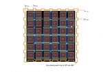
Here's a layout for 4 equal MIM S&H and feedBack caps C1..C4 for a diff. S&H OTA - divided into 8 single caps, each:
S&H-cap-layout.png
C5 & C6 are used as couple caps from the outputs to the CMFB circuit; the 2 "D" caps are dummies.

Instead of dummy caps around all sides, an adapted MT & M3 guard ring had been built, together with passably equal lengths (cap-values) of the 2 nodes to the input gates:
caparray_with_guardRing.jpg
 

Erikl,

Thank you for your message.

What are the advantages/disadvantages of this technique versus dummies all around the sides ?

Thank you.

- - - Updated - - -

Erikl,

You said C1...C4 are 4 equal MIM S&H and feedBack caps C1..C4 for a diff. S&H OTA.

So which capacitor is which ? C1 is sampling, integrating capacitor ? C2 is sampling, integrating capacitor ? C3 is sampling, integrating capacitor ? C4 is sampling, integrating capacitor ?

It might not matter, but just wondering to picture it in my mind.

Also C5, C6 are part of the Switched Capacitor CMFB circuit ? or just dc/ac coupling to the CMFB ?

Thank you.
 

What are the advantages/disadvantages of this technique versus dummies all around the sides ?
Advantage: Less silicon space. Disadvantage: Geometry and spacing have to be chosen thoroughly.

You said C1...C4 are 4 equal MIM S&H and feedBack caps C1..C4 for a diff. S&H OTA.

So which capacitor is which ? C1 is sampling, integrating capacitor ? C2 is sampling, integrating capacitor ? C3 is sampling, integrating capacitor ? C4 is sampling, integrating capacitor ?
Doesn't really matter: They all are the same size. Two of them for S&H, the two others for feedback.

Also C5, C6 are part of the Switched Capacitor CMFB circuit ? or just dc/ac coupling to the CMFB ?
The latter: diff OTA outputs ac coupling to CMFB input - as already mentioned above.
 

"...Instead of dummy caps around all sides, an adapted MT & M3 guard ring had been built"

What is MT and M3 guard ring - M3 is metal 3 - what is MT ?

Thank you.
 

Status
Not open for further replies.

Part and Inventory Search

Welcome to EDABoard.com

Sponsor

Back
Top