Continue to Site

Welcome to EDAboard.com

Welcome to our site! EDAboard.com is an international Electronics Discussion Forum focused on EDA software, circuits, schematics, books, theory, papers, asic, pld, 8051, DSP, Network, RF, Analog Design, PCB, Service Manuals... and a whole lot more! To participate you need to register. Registration is free. Click here to register now.

Short Circuits Three - KC5519 kit (audio amplifier with pre-amplifier)

Status
Not open for further replies.

boylesg

Advanced Member level 4
Joined
Jul 15, 2012
Messages
1,023
Helped
5
Reputation
10
Reaction score
6
Trophy points
1,318
Location
Epping, Victoria, Australia
Activity points
11,697
Is anyone familiar with this?

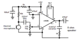
I am trying to get this working with 2 x electret microphone attached to PCB connectors 2 & 3.

I have added 2 wires to the positive supply pin, connected the end of these to 2 x 27k resistors and then connected the other end of these to the positive of the positive of the PCB connectors.

This gives me about 6V on the positive of the electrets when they are clamped into the connector.

I am getting output on my speaker (which came from a television set) but the output is very scratchy and talking into the electret microphones does not produce recognizable voice output on the speaker.

The circuit is meant to take 2 x microphones (L & R), since it has two input connectors on the pre-amplifier stage.

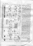
Sorry but I can't find a schematic of this online - I will have to scan the printed schematic that came with the kit.

But I am hoping that some one is played with this kit and is familiar with it.

- - - Updated - - -

Oh I think it has just dawned on me what I did wrong. I powered to electret with 12V but the opamp in the pre-amplifer is powered with 5V.
 

An electret mic draws 0.5mA or a little less and needs at least 2V across it. If a 27k resistor feeds the mic from 12V then the voltage across the mic is 12V - (0.5mA x 27K)= NOTHING!
If the mic has 4V across it then the resistor from 12V is (12V - 4V)/0.5mA= 16k.

Maybe the kit amplifier was built with a transistor or polarized capacitor connected backwards?
Maybe the kit amplifier has a DC coupled input for a dynamic mic that has no DC voltage? Then you need an input coupling capacitor to block the DC on the electret mic.
 

Thanks AudioGuru. The printout says the following:

Microphone bias current
-----------------------
The Pre-Champion is a relatively simple design and doesn't have onboard support for balanced microphones, electret bias current and so on. However most mics have a built-in power supply or require no bias. in which case you just connect them straight to one of the inputs. If you want to use an electret you wire a 10k resistor between the regulators +5V pin and the terminal 1 (the upper terminal) of either CON2 or CON3.


OK so I did that but no difference - the electrets are totally insensitive and no recognizable voice output comes from the speaker.

So I am at a loss. The only other thing I can think of is that the electrets I got from ebay are $hit or just incompatible. But I didn't think there was much difference between electret microphones.
 

will have to scan the printed schematic that came with the kit.
You should do that.

The kit description says "Signal Input Level 52mV", not actually microphone sensitivity.

- - - Updated - - -

O.K., pre-amp sensitivity 2 - 5 mV, should work.
 

An electret mic has a Jfet inside as an impedance converter. The Jfet must be powered with a bias current of about 0.5mA with a few DC volts that the preamp does not provide.
This simple preamp is made for a dynamic mic (coil and magnet like a tiny speaker) that generates a signal.
 

An electret mic has a Jfet inside as an impedance converter. The Jfet must be powered with a bias current of about 0.5mA with a few DC volts that the preamp does not provide.
This simple preamp is made for a dynamic mic (coil and magnet like a tiny speaker) that generates a signal.
But the printed documentation says that you can use an electret microphone with it.

And did you find the circuit schematic online or did you have a copy of Short Circuits Three lying around?

What would be a suitable dynamic microphone to use?

I had one lying around and it says it has an impedance of 200R, but I get no out put from the the speaker.

- - - Updated - - -

You should do that.

The kit description says "Signal Input Level 52mV", not actually microphone sensitivity.

- - - Updated - - -

O.K., pre-amp sensitivity 2 - 5 mV, should work.

Schematic attached

So what I did was solder a wire connector from LP2950 'OUT' to 'CON1' +, and another wire from LP2950 'GND' to 'CON1' -.
They are conveniently close on the PCB.
I soldered in a screw terminal block into 'CON1' - normally you would only solder a terminal block here if you separate the preamp part of the PCB from the amp part of the PCB.
But a terminal block here makes for a convenient place to access the 5V from the voltage regulator to power the electrets through easily changeable resistors.
 

Attachments

  • Champ005.jpg
    Champ005.jpg
    559.1 KB · Views: 340
Last edited:

You have two microphones that do not work then probably there is something wrong with the kit amplifier.
 

You have two microphones that do not work then probably there is something wrong with the kit amplifier.

OK well if I have to actually touch my lips on the microphone to get any output coming through the speaker then where should I start looking in the circuit?

Do you have a circuit, that you have successfully used yourself, to amplify an electret microphone to an 8R speaker that I could try on my bread board?

Incidentally some time ago I tried the Jacobs Ladder kit and I could not get that to work either. So it aint looking good for these Short Circuits project kits then is it!

- - - Updated - - -

I had a bit of success. I also got the Champ Pre-amp kit - which is specifically designed for an electret.

Hooked it up to a set of mobile phone ear phones and it works brilliantly.

So probably what I need to do is break off the pre-amp part of the PCB I have been using and use the above as the pre-amp for the Champ amplifier instead.

So the problem appears to be that the tech people wrote the damn manual for the kit, and tech people generally write terrible manuals!
 

Hello boylesg,
The Kit: KC5519 is not featured in Short Circuits 3, unless they did a revamp of that projects magazine.
The kit you're referring to is an updated version of the early champ and pre-champ amplifiers.
Silicon Chip magazine designed the updated version with different audio IC's (much better quality ones),
and basically gave it a much improved sound output.
I've checked the notes and errata on all projects of 2013 and there are no mistakes with the original design.

You don't need to use two microphones on this project, as the two pre-amplifier op-amps will end up being
summed together anyway, so you won't get stereo out, as the project was designed for mono operation.
To install an electret mic, please see the picture below:

Electret

With all the electret microphones I've used are normally polarity conscious, so make sure you insert it the
right way around.
You can usually tell by one of the pins being attached to the body of the mic via a small track.

Please let us know how you get on.
Regards,
Relayer

Thanks Relayer.

This issue is driving me nuts!

I was told at Jaycar that the Pre-champ kit would work with the Champ Amplifier with Pre-Amp.

The Pre-champ or KC5166 simply consists of a BC548 and BC558 and this kit is working beautifully with my electret microphone, powered with 12V and with the output hooked up to a set of ear phones.

But any attempt to hook the output up with the Champ Amplifier (without or without the Pre-amplfier) is defeating me - I get no output at all on a 8R speaker hooked up to the speaker connector.

I have also tried wiring up a few simple amplifiers on my bread board and passing the output of the Pre-Champ kit, through the bread board amplifier and then to an 8R speaker.

That includes a AC coupled non-inverting LM386 amplifier straight from the datasheet, a transistor version of the Champ amplifier using BC327/BC337 as the output stage and a simple BD139/BD140 push pull pair biased with 1N1418.

But the first two resulted in really scratchy voice reproduction and the last resulted in no output at all.

The problem is I just don't know enough about amplifiers to design a circuit from scratch.

Any suggestion on how I could build an amplifier to successfully amplify the output of my Pre-Champ kit through an 8R speaker would be gratefully received - LM386 based or transistor based....I don't care as long as the voice repdiction in the 8R speaker is as crisp as the the Pre-Champ produces through the earphones.
 

You do not show your schematics so we cannot show you what causes their problems.
An LM386 has a gain of 20 times and works well with a line level input. When a 10uF capacitor is added between pin1 and pin 8 the gain is increased to 200 and it works well as an amplifier for an electret mic shown here:
 

Attachments

  • LM386 with mic.PNG
    LM386 with mic.PNG
    16.6 KB · Views: 187

This is the schematic for the Pre-Champ Preamplifier - it works nicely with the electret.......oh I just noticed......scratch the left most 100k to ground and replace it with a 10k from 12V.

ELEC00041.jpg


This is the schematic of the The Champ (with Preamplifier) that won't work with the above......and I would love to try and understand why it won't work using or not using the Preamplifier part.

From the LM386 datasheet, why won't the AC coupled non-inverting amplifier work with the output from Pre-Champ Preamplifier? I.E. It produces poor sound quality through the 8R speaker.
 

Attachments

  • Champ005.jpg
    Champ005.jpg
    559.1 KB · Views: 220

The output capacitor value on the preamp is crazy at 470uF!! Calculate how long it needs to charge. It will be fully charged 110 seconds after the circuit is powered when the amplifier begins playing properly.
For a low frequency cutoff at 34Hz then the capacitor is calculated to be 4700 times less at 0.1uF when it will be fully charged in 0.024 of a second.

Sorry the circuit is almost identical to the one in the printed doc that came with the kit. In the doco that cap is 10uF. Didn't look close enough at the details and just assumed it was the PreChamp schematic.

The pre-champ works perfectly - it is not the issue. Getting it to work with the Champ is the issue.

I also fiddled around with my Champ Amplifier PCB and noticed the voltage on pin1 of AN7511 is 0.7V where as I assume it is meant to be 12V, or close to it, across the 100k resistor.

It suggests to me I have overloaded the chip previously and I need to replace it?
 

The schematic you posted has a 470nF capacitor feeding the power amplifier, not 470uF which is 1000 times more shown in your preamp schematic.
The schematic does not show what pin1 "STANDBY" connects to and the datasheet of the Japanese power amp does not say if it is destroyed if STANDBY is higher than 5V.
 

This is the Prechamp schematic.....minus all the parts outside the dotted square.

101590_3lo.jpg


OK simple question.....possibly not as simple to answer.

How do I go about connecting the circuit in the dotted square (Prechamp Preamplifier) to the Champ amplifier in the attached schematic and getting some output on the speakers?

Note that the Champ Amplifier kit I obtained had a built in, but detachable, Pre-amplifier and I have separated off that built in pre-amplifier.
 

Attachments

  • Champ005.jpg
    Champ005.jpg
    559.1 KB · Views: 175

Without a volume control there will be too much gain. I show how to connect them and how to reduce the gain:
 

Attachments

  • Champ amp with pre-champ.png
    Champ amp with pre-champ.png
    154.9 KB · Views: 427

Status
Not open for further replies.

Part and Inventory Search

Welcome to EDABoard.com

Sponsor

Back
Top