Continue to Site

Welcome to EDAboard.com

Welcome to our site! EDAboard.com is an international Electronics Discussion Forum focused on EDA software, circuits, schematics, books, theory, papers, asic, pld, 8051, DSP, Network, RF, Analog Design, PCB, Service Manuals... and a whole lot more! To participate you need to register. Registration is free. Click here to register now.

[SOLVED] BLDC: Flyback recovery

Status
Not open for further replies.

righteous

Full Member level 2
Joined
Nov 29, 2017
Messages
130
Helped
0
Reputation
0
Reaction score
0
Trophy points
16
Activity points
1,282
Gents,

I want to recover as much flyback current as possible from my BLDC, so far I have 200mA going in and I'm only able to recover 1-3 mA's before the voltage after the (hand drawn) diode drops below supply voltage, which is disappointing.

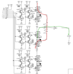
This is the driver stage of my BLDC controller, and I have taken phase 1 as an example
Screenshot from 2018-04-13 11-15-26.png

In red the coil gets energized, and the green is where I expect the flyback current to go. Q7 is OFF, but I expect the body diode to conduct.

I have made this online calculation (NB: the switching pulse is V(ds) and not V(g))

Screenshot from 2018-04-13 11-29-26.png

And the scope shows that I should be right on the money.

SDS00019.PNG

CH1 and CH2 is voltage across a 1 ohm shunt resistor on the high side. The WHITE trace is CH1 minus CH2

And CH3 is the gate switching signal for Q12 the low side FET.

So...where is my flyback current?
 

Hi,

Sorry for repeating me: You can´t expect a motor operates the same as an inductance. It has been discussed already.

Added:
Maybe this helps you to understand:
A motor is made to transform electrical energy --> to magnetic energy --> rotating mechanical energy. It is made to consume electrical energy that is never given back to the electrical circuit.

In oppsite your "storage inductance". It is made to store electrical energy and give it back to the circuit - as much as possible.

Klaus
 

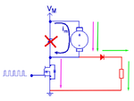
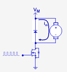
First of all, your hand drawing is wrong.

You have drawn this:
ActualHandDrawing.png

I guess you want this:
Intent.png

That being said, check your circuit again.
 
Last edited:
Hi,

Sorry for repeating me: You can´t expect a motor operates the same as an inductance. It has been discussed already.

Added:
Maybe this helps you to understand:
A motor is made to transform electrical energy --> to magnetic energy --> rotating mechanical energy. It is made to consume electrical energy that is never given back to the electrical circuit.

In oppsite your "storage inductance". It is made to store electrical energy and give it back to the circuit - as much as possible.

Klaus

Yes, it has been discussed for a conventionally commutated and constructed DC motor, this is an electronically commutated BLDC with AIR CORES, no mutual induction, no stray inductance, just a simple AIR CORE COILS, three individual of them actually

I will not rule out that I'm the stupid one here, so would you kindly explain to me why a simple AIR CORE COIL does not work the same way whether it is situated in an BLDC enclosure or not?

You can see from the scope shot that the AIR CORE COIL acts exactly the same whether it is in a motor, or in a boost configuration. Where exactly is the electrical energy (I assume you mean P=U*I) consumed in the scope shot?

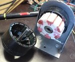
For the sake of clarity, here is my stator and rotor:
IMG_20180413_143129.jpg

- - - Updated - - -

First of all, your hand drawing is wrong.

You have drawn this:
View attachment 145983

I guess you want this:
View attachment 145984

That being said, check your circuit again.

My God, you are right!
 
Last edited:

The basic topology for maximal energy recovery is a H- respectively three-phase bridge. The first schematic in post #1 does it, without any additional components.

Not sure what your problem is, I guess you didn't yet analyze the bridge driver behavior completely.
 

Not sure what your problem is, I guess you didn't yet analyze the bridge driver behavior completely.

I was under the impression that the flyback current was trapped in the upper half of the bridge, so I wanted to set it free. I don't know if I did a complete behavior analysis, there seems to be diverging opinions, I can't really judge, so I thought an experiment was called for.
 

Hi,

I don't think there are divergent opinions.

There is a motor with coils, but the coils of a motor don't operate like a "pure inductor".
The difference is the rotating magnetic field of a motor. You can't ignore this.
And every rotating magnetic field causes voltage --> the motor becomes a generator.
The generator voltage acts against the excitation voltage.

Thus a non_moving motor draws more current than a moving motor.

******
Inductor:
When you excite a pure inductor...and then disconnect the power supply and short the inductor winding (either actively with a half bridge or passively with a flywheel diode)
Then all magnetic field slowly collapses. The voltage across the inductor in this case is inverted (only) and the current is non inverted (only).Until the energy stored in the inductor collapses and voltage as well as current become zero. Steady state.

If you do the same with a motor.
Then the voltage is for a short time inverted. The magnetive field collapses very fast because there is relatively high voltage across the internal stray inductance. The energy isused to power the rotation. (But as said only for a very short time compared to a pure inductor).
But then something happens that doesn't happen with a pure inductor:
The motor acts as a generator..the voltage becomes positive ... and if now it is actively shorted externally (because of voltage direction a flywheeld diode is high ohmic now) --> the current becomes inverted...the rotation will be decelerated...
- and in opposite to a pure inductance - this breaking current may become (much) higher than the current before you disconnected the power supply. It may burn the transistors.

I said "with a motor the stored energy in the inductance" collapses very fast. Howfast depends on the motor construction and the motor power stage.
Thus you should not use low frequency half bridge PWM to drive a motor...the frequency needs to be fast enough that the current never becomes negative (during normal operation) --> avoid the "acceleration-deceleration-acceleration-deceleration.." situation.

What (else) can I do, that you stop to electrically compare a pure inductance with a motor? Please accept that it behaves differently.
If you don't believe ... I recommend to use a scope to show U and I and the timing ... compare the measurement results with your calculations.

Maybe a good test could be
* measure the inductance of a motor
* find an inductor with compareable inductance
* do measurements with a rotating motor
* do the same tests with the inductor

Klaus
 

that the AIR CORE COIL acts exactly the same whether it is in a motor, or in a boost configuration...

This is true if and only if the rotor is removed (or held fixed- not moving).

A moving magnetic field couples with the oscillating magnetic field produced in the coils. And that makes a lot of difference.

There is no other way for the rotor to receive energy from the coils...
 

It's not an "air core" when the windings are in position with the magnets nearby - also there is likely some steel inside the plastic of the winding structure to increase motor efficiency to complete the magnetic circuit, you can only really recover the energy in the leakage and perhaps a small fraction of that in the steel/magnet cores if you operate the motor so that it doesn't move, i.e. opposing current pulses in the phases then you might be able to operate it as a crude flyback - but why do this?

If you need an aux supply - better to design one off the source.
 

What (else) can I do, that you stop to electrically compare a pure inductance with a motor? Please accept that it behaves differently.

My dear Klaus, first of all, you know that I value your opinion, and I don't want to antagonize anyone, if my post is doing so, then I would kindly request you to delete it, I don't mind.

Secondly, I'm in agreement with your theory, it is all logical and coherent.

If you don't believe ... I recommend to use a scope to show U and I and the timing ... compare the measurement results with your calculations.

Maybe a good test could be
* measure the inductance of a motor
* find an inductor with compareable inductance
* do measurements with a rotating motor
* do the same tests with the inductor

That is a brilliant experiment that would eradicate any doubts, therefore I performed it before I started.
 

Hi,

My dear Klaus, first of all, you know that I value your opinion, and I don't want to antagonize anyone, if my post is doing so, then I would kindly request you to delete it, I don't mind.
No, I'm not angry and I never was. I'm just clueless how to explain it the correct way.
Thus there is no need to delete anything.
Additionally I want to apologise in case you feel bad about my posts - this was and is not my intention.

That is a brilliant experiment that would eradicate any doubts, therefore I performed it before I started.
That's good.
Do you have any results or scope pictures to discuss about?
Did you see any difference?
It think it's a good way to discuss about real measurements than about the theory.

Klaus
 

I'm just clueless how to explain it the correct way.

But I said that you have already explained it very clearly in theoretical terms and that I agree with you. (It's not you, it's me that is "incorrect" ;-)

Did you see any difference?

Nope. The experiment was simplified and conducted in a way so that the same physical coil was used i.e: Disconnect BLDC completely, connect one of the phases (i.e. 'coil' - whilst still situated in the BLDC enclosure) to your boost circuit, tune it to 110KHz and 30% duty cycle, and take note of input power (P=U*I) and output power, then you get ~97% efficiency. Then spin the rotor at the shaft and take note of input power and output power again, then compare with the first results and note the difference.
 

Hi,

Nope. The experiment was simplified and conducted in a way so that the same physical coil was used i.e: Disconnect BLDC completely, connect one of the phases (i.e. 'coil' - whilst still situated in the BLDC enclosure) to your boost circuit, tune it to 110KHz and 30% duty cycle, and take note of input power (P=U*I) and output power, then you get ~97% efficiency. Then spin the rotor at the shaft and take note of input power and output power again, then compare with the first results and note the difference.

Just giving 30% duty cycle to one phase ... will not show the same results as when you give a "rotating magnet field" to all three phases.
There are times when the coil magnetism tries to accelerate the motor, and there are times when the magnetism of the coil trues to decelerate the motor.
Thus the coil moves energy from the power supply to the rotation and back. With 0%, 10% or 30% the motor will not run faster or slower.
The average energy is not involved in the rotation energy. Thus the energy flow is zero (not taking care about losses)

This situation is different when you apply a rotating magnet field to the coils. Then the electrical magnet rotation is synchronous to the rotor magnet field (but phase shifted).

Klaus
 

Just giving 30% duty cycle to one phase ... will not show the same results as when you give a "rotating magnet field" to all three phases.

Klaus, in a three phase BLDC only one phase is energized at any given time. But let's say you are right about everything, I have no problem with that, the energy flow is always zero, I stand corrected, case closed.
 

In the usual delta wiring, it's not possible to energize only one coil at a time. But I don't see how this makes a difference.
 

In the usual delta wiring, it's not possible to energize only one coil at a time. But I don't see how this makes a difference.

As I said; you are correct. It doesn't make any difference. You have convinced me, it was a very silly idea from my side to begin with and I was wasting everybody's time, I'm sorry about that.

On popular demand, I have now thrown the circuit board and BLDC on the scrap heap, as we speak gypsies are reclaiming the copper and gold for resale.
 

It will still be possible to recover some energy from the coils when the rotor is slowing down - and if you are successful in that, the rotor will experience a brake. The motor will function like a generator but that is a different case altogether.
 

As previously mentioned, bridge circuit does recovery of stored inductive energy as well as regenerative breaking. Some energy is of course lost in winding resistance, iron core and switches.
 

Status
Not open for further replies.

Similar threads

Part and Inventory Search

Welcome to EDABoard.com

Sponsor

Back
Top