Continue to Site

Welcome to EDAboard.com

Welcome to our site! EDAboard.com is an international Electronics Discussion Forum focused on EDA software, circuits, schematics, books, theory, papers, asic, pld, 8051, DSP, Network, RF, Analog Design, PCB, Service Manuals... and a whole lot more! To participate you need to register. Registration is free. Click here to register now.

[SOLVED] BLDC: Once and for all EMF, BEMF, CEMF or Flyback?

Status
Not open for further replies.

righteous

Full Member level 2
Joined
Nov 29, 2017
Messages
130
Helped
0
Reputation
0
Reaction score
0
Trophy points
16
Activity points
1,282
Gents,

I'm working on my BLDC and learn at the same time, but I'm getting more and more confused due to the liberal interchange of terms i.e. EMF, BEMF, CEMF and Flyback. I'm trying to keep the TI blog So, Which PWM Technique is Best? as authoritative as the terms are explained before they are utilized, except when they are not... as the case is here.

Definition of Terms:
EMF = Is the energy produced in the coil by the passing magnets (But some people also use the term BEMF/CEMF deliberately just to confuse me ;-)
BEMF= Back-EMF Is the energy expelled by the coil when its magnetic field collapses, alternatively the term "flyback" can be used.

In Part II of the blog it states

Texas Instruments said:
[....]the inductive flyback current is “trapped” in the top half of the H-Bridge, and never flows back into the DC bus

So my question is; is this a depiction of EMF or BEMF when Q2 is OFF? As the text says "flyback" and the drawing states "Motor Back EMF", so do they mean "Motor Back EMF" as in BEMF=Flyback? Or is it another case of term confusion where "Motor Back EMF" as in EMF definition?

ANIMATED GIF PICTURE (You may need to tell your browser to play gif's)
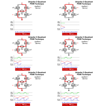
Unipolar 2Q PWM (Reverse).gif

And if it is BEMF, what happens to that trapped energy? Is it being put to use in driving the motor, or does it simply just loop around until it "evaporates" as there is no ground potential (current loop)?
 

In the quot from TI, can you see the word current aside the word flyback ?
Can you see that current is not the same as voltage ?

Can you see then, that using flyback in conjunction with voltage leads you to confusion ?
is this a depiction of EMF or BEMF when Q2 is OFF?
As it was explained in your other thread, in motors, the armature voltage (i.e. voltage between "+" and "-" terminals) of a motor is simply called:
"e.m.f" or "armature e.m.f" or "counter e.m.f" or "back e.m.f" , all being the same thing.

what happens to that trapped energy?
Look again in the "animated" diagram, particularly at the "Motor current" one.
 
Thank you for your reply, I really appreciate it.

Can you see then, that using flyback in conjunction with voltage leads you to confusion ?

Yes, I see now, let me try to recap to see if I understood correctly:

#1 The VOLTAGE on the motor terminals is called EMF/BEMF/CEMF/AEMF and occurs when the coil is being excited by a passing magnet.

#2 The EMF/BEMF/CEMF/AEMF is accompanied by a CURRENT of the same phase, when a load is applied to the motor terminals

#3 The FLYBACK is a CURRENT released by the coil when its magnetic field collapses

#4 When the FLYBACK CURRENT is "trapped" it enters the armature (coil) and creates a VOLTAGE (also called EMF/BEMF/CEMF/AEMF?) that creates rotational motion

Would that be about right?

Also what adds to my confusion is that in the animated drawing, the red paths are CURRENT, and the caption is "Motor Back EMF" which is a VOLTAGE.
 

#1 The VOLTAGE on the motor terminals is called EMF/BEMF/CEMF/AEMF and occurs when the coil is being excited by a passing magnet.
Yes and is the same as the voltage applied by the user (excitation voltage), under the assumption that there is no loss in the winding of the motor itself, nor the brushes.

#2 The EMF/BEMF/CEMF/AEMF is accompanied by a CURRENT of the same phase, when a load is applied to the motor terminals
What do you mean by "Load to the motor terminals" ? The voltage source ? WHen you apply the voltage source to the motor, there will be a current through its windings, of course.
#3 The FLYBACK is a CURRENT released by the coil when its magnetic field collapses
The flyback current, is a current that is stored in the parasitic inductances or in the winding excitation in case of a series excited motor (i.e. not permanent magnet one). It is released by the parasitic inductances (or the winding excitaticion...).

#4 When the FLYBACK CURRENT is "trapped" it enters the armature (coil) and creates a VOLTAGE (also called EMF/BEMF/CEMF/AEMF?) that creates rotational motion
NO.
The flyback current is a parasitic current.

Here is how the rotational motion is created (motor is not spinning):
1) Rotor lies inside a magnetic filed (produced either by permanent magnets or by another windings "stator windings")
2) Voltage source applied to the motor terminals
3) Current flows into the rotor windings (armature).
4) Motion is created due to Lorentz law.
5) back e.m.f. (or alternative names) is created due to Farady law.

- - - Updated - - -

the red paths are CURRENT, and the caption is "Motor Back EMF" which is a VOLTAGE.
They are referring to the "+" and "-" terminals which is a voltage.
 
What do you mean by "Load to the motor terminals" ?

I mean resistive load as in a dynamo, I assume it's only producing voltage until a load is applied if the motor (now dynamo) were powered at the shaft only.

The flyback current, is a current that is stored in the parasitic inductances or in the winding excitation in case of a series excited motor (i.e. not permanent magnet one). It is released by the parasitic inductances (or the winding excitaticion...).

Ahh, new term for me "series excited motor"... so I assume a BLDC is a "separately excited motor" and the flyback current is released when you turn off the supply current?

They are referring to the "+" and "-" terminals which is a voltage.

Another proof that communication is difficult, I would never have made that connection when "Motor Back EMF" is right smack in the middle of the figure, I thought that "Motor Back EMF" was the main topic shown.
 

I doubt that you won't get much insights by analyzing the meaning of terms. You better set up an equivalent circuit of the motor and try to understand how the waveforms shown in the animated schematic come about.

The simplified waveforms suggest a constant motor e.m.f. (of about 2/3 the bus voltage), zero armature resistance, an armature inductance according to the shown current slope. The switch 2 duty cycle be 2/3 on, 1/3 off.
 

I doubt that you won't get much insights by analyzing the meaning of terms. You better set up an equivalent circuit of the motor and try to understand how the waveforms shown in the animated schematic come about.

Well, I feel that Mr. CataM helped me a lot by clarifying the terms for me. My great conceptual problem has always been terms with 50/50 chance of being correct e.g. like BEMF/Flyback and their associated voltage/current. And when I learn it, it simply doesn't stick to my brain, and the next time I have to guess, I would have forgotten it, then I guess wrong, that's just the way I'm born, I can't help it, sorry.

But I have followed your advise, and have a real live circuit with real waveforms and some real questions, I will open a new thread tomorrow because now I'm very tired.

Goodnight.
 

Status
Not open for further replies.

Similar threads

Part and Inventory Search

Welcome to EDABoard.com

Sponsor

Back
Top