sherif96
Member level 4
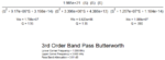
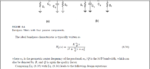
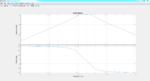
I am designing a third order butterworth bandpass filter, I derived the transfer function using matlab which was composed of a 6th order which would give 3 quadratic equations, the resulting transfer function of the 3 quadratic equations are attached, I just have a quick question in regards to some basics, in the attachment of the transfer function, why the Wo and q differs from one stage to the other? and how can the wo/q term which is the coefficient of S in the denominator is not equal to the nominator which also should be wo/q based on the general formula of the bandpass filters? I understand this would result in some gain in the bode plot of the quadratic equation alone,however if i plot the second and third stage they both have a gain bigger than 0db while the first stage has a gain of 0db, the resulting gain of all stages is 0db which is what I wanted actually but I cannot understand how those building blocks results in my desired design when 2 of 3 stages have gain bigger than 0 dB?