Continue to Site

Welcome to EDAboard.com

Welcome to our site! EDAboard.com is an international Electronics Discussion Forum focused on EDA software, circuits, schematics, books, theory, papers, asic, pld, 8051, DSP, Network, RF, Analog Design, PCB, Service Manuals... and a whole lot more! To participate you need to register. Registration is free. Click here to register now.

[SOLVED] Problem with created component when the layout is generated

Status
Not open for further replies.

ndequeiroz

Junior Member level 3
Joined
May 11, 2017
Messages
25
Helped
0
Reputation
0
Reaction score
0
Trophy points
1
Activity points
201
Hi,

I tried to create the layout of a component (Schottky diode on SOD882 package). For that i created a schematic to model the parameters, a symbol, and a layout to draw the pads, Solder mask, etc...

SMS7630.png

SMS7630Symbol.png

First of all for the layout of the component i used:

Cond layer to pads
Solder mask layer to solder mask
Leads layer to PCB pad metalization

SMS7630Layout.png

Is it correct?

When i click to generate the layout of my board that thing happens:

IssueOnLayout.png

What am i doing wrong?

Thanks
 

ADS doesn't understand that your manually drawn layout cell IS the layout, and tries to place the model components into the diode layout.
There are some settings in File > Customize Pcell for the layout, but I couldn't get that to work.

You should contact Keysight support for your case.

art_issue.PNG
 

ADS doesn't understand that your manually drawn layout cell IS the layout, and tries to place the model components into the diode layout.
There are some settings in File > Customize Pcell for the layout, but I couldn't get that to work.

You should contact Keysight support for your case.

View attachment 145737

Thank you Dr. Volker, i will try to do that.


I realize that my footprint is different of yours. This is the datasheet that i used.

SMS7630Footprint.png

Cause i'm new in PCB design i'm not so sure about my footprint layout, is that correct?


And just one more question, what is the difference between VIAGND and VIAFC, i read the documentation and it's just the range of usage?
 

Don't worry about the footprint size, I just created random polygon size to test the workflow. So my dimensions are NOT correct!

And just one more question, what is the difference between VIAGND and VIAFC, i read the documentation and it's just the range of usage?

I used VIAFC for routing a trace from one side to the other, where both sides are signal lines (not ground). The VIAGND is a via from one side to a ground layer, so this has no pad on the ground layer if I remember correctly.
 
There are some settings in File > Customize Pcell for the layout, but I couldn't get that to work

Everything described here is correct for using a manually drawn layout view to represent a custom device but one step is missing. When you set the Artwork Type to Referenced/fixed Pcell it is necessary to define the Design name as the name of the custom cell being created. It needs to be referenced to itself for the layout view to be utilized to represent the device correctly.
 
Everything described here is correct for using a manually drawn layout view to represent a custom device but one step is missing. When you set the Artwork Type to Referenced/fixed Pcell it is necessary to define the Design name as the name of the custom cell being created. It needs to be referenced to itself for the layout view to be utilized to represent the device correctly.

This option is on the layout view? 'cause i don't found it... I'm using ADS 2011.05
 

See my post #2, window on the bottom right, the empty "design name" field.

Thanks RealAEL!
 

This option is on the layout view? 'cause i don't found it... I'm using ADS 2011.05

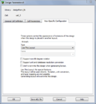
It is there in ADS 2011 but it was in a slightly different location. From the Layout window select the menu function "File > Design Parameters...". In this window there are three tabs, select the right most tab labelled "View-Specific Configuration". In there you will see locations to enter Artwork Type and Name. For the Type select "Referenced/Fixed" and then enter the layout cell name for referencing the current layout view.

view_tab_for_subnetwork.PNG
 

Status
Not open for further replies.

Part and Inventory Search

Welcome to EDABoard.com

Sponsor

Back
Top