Continue to Site

Welcome to EDAboard.com

Welcome to our site! EDAboard.com is an international Electronics Discussion Forum focused on EDA software, circuits, schematics, books, theory, papers, asic, pld, 8051, DSP, Network, RF, Analog Design, PCB, Service Manuals... and a whole lot more! To participate you need to register. Registration is free. Click here to register now.

doubt on this simple verilog pipeling

Status
Not open for further replies.

hcu

Advanced Member level 4
Joined
Feb 28, 2017
Messages
101
Helped
0
Reputation
0
Reaction score
0
Trophy points
16
Activity points
874
Hi all,

Code:
// Code your design here
module data_sampling_doubt1 (
  input clk,
  input rst,
  input [3:0] data_in,
  input vld,
  input [1:0] opcode,
  output reg [3:0] data_out1,
  output reg [3:0] data_out2
);
  
  reg [3:0] data_temp;


  always@(posedge clk)
  begin
    if(rst)
      	data_out1 <= 0;
  	else if(vld)
    	case(opcode)
          
      		2'b11: data_out1 <= data_in;
      		default: data_out1 <= 'hF;
    	  
    	endcase
    else
      	data_out1 <= 'hE;
  end
  
  // pipelining the input port data into a data_temp register//
    always@(posedge clk) begin
    if(rst)
      data_temp <= 0;
    else
      data_temp <= data_in;
  end 
  always@(posedge clk)
  begin
    if(rst)
      	data_out2 <= 0;
  	else if(vld)
    	case(opcode)
          
      		2'b11: data_out2 <=  data_temp;
      		default: data_out2 <= 'hF;
    	  
    	endcase
    else
      	data_out1 <= 'hE;
  end
endmodule

Code:
// Code your testbench here
// or browse Examples
module test1();
  
   reg clk;
  reg rst;
  reg [3:0] data_in;
  reg vld;
  reg [1:0] opcode;
  wire [3:0] data_out1;
  wire [3:0] data_out2;
  
 data_sampling_doubt1 dut(
  clk,
  rst,
  data_in,
  vld,
  opcode,
  data_out1,
  data_out2
 );
  
  initial begin
    $dumpfile("dump1.vcd");
    $dumpvars;
    
    rst =1;
    data_in = 0;
    vld = 0;
    opcode = 0;
    #100 rst =0;
    #50;
    data_in = 'hb;
    vld = 1;
    opcode = 'b11;
    #20;
    vld = 0;
    opcode = 0;
    data_in = 'hc;
    #20;
    vld = 1;
    opcode = 0;
    data_in = 'hd;
        #20;
    vld = 0;
    opcode = 0;
    data_in = 'h0;
    #200;
    $finish;
  end
  
  initial
    clk =0;
  always #10 clk = ~ clk;
endmodule
Screenshot.png


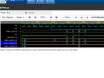
1.why data_out2 result is not same as data_out1.?
2. how clock (looks) samples data from a io port and from a register ?
 

A. You have a race condition with the inputs and clock to your dut which is why the sim shows FF data transfers occurring on the leading edge of the signals. Never line up testbench signals with the active clock edge.

B. You didn't pipeline vld and opcode too, so the data and valid are no longer active at the same time to load the second register.

thank you,

I learn a point from the Point A ,you mentioned.


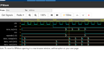
coming to point B, yes,i not pipelined vld and opcode. but from the waveform at 150ns data_temp(register) already holds the value b at leading edge. this also causes race condition ?
Screenshot-3.png

one trivial question: at 150ns clock is sampling data "0" but not "b" from the data_temp register ?
 

thank you,

I learn a point from the Point A ,you mentioned.


coming to point B, yes,i not pipelined vld and opcode. but from the waveform at 150ns data_temp(register) already holds the value b at leading edge. this also causes race condition ?
View attachment 145460

one trivial question: at 150ns clock is sampling data "0" but not "b" from the data_temp register ?

I'm confused what is your question, you seem to be asking the same question two different ways.

If you have issues with understanding simulation waveforms then add #1 to every assignment so you can visualize (use this only for understanding purposes, don't use it otherwise) the delay that the circuit has in real life.

In simulation when the clock causes a FF to capture the D input and place it on the Q output the Q output will change its state to the D input value after a simulation "delta" cycle. This simulation cycle does not show up in the waveform as it's a 0ns time interval for scheduling events. So the waveform result is the Q output changes at the same time as the clock, but in reality it's changing some simulation scheduling cycles after the clock edge and won't be seen at its updated value until the next clock edge. (Hope you can understand that explanation).

The way you've currently written you code you are not using the VLD and OPCODE in a pipeline you are using them as a clock enable to a two stage shift register, which is why I mentioned you did not pipeline VLD and OPCODE.

Pipelining usually refers to adding register stages to break up a slow circuit to improve throughput by adding latency. This means that the newly pipelined circuit can get new data in on every clock cycle and some number of clock cycles later the results will appear (for each input) on every output clock. What you are doing is making the circuit update only when the VLD and OPCODE are correct. This slows the entire circuit down by creating a multicycle path between the register stages and is not considered pipelining.
 
Status
Not open for further replies.

Part and Inventory Search

Welcome to EDABoard.com

Sponsor

Back
Top