Continue to Site

Welcome to EDAboard.com

Welcome to our site! EDAboard.com is an international Electronics Discussion Forum focused on EDA software, circuits, schematics, books, theory, papers, asic, pld, 8051, DSP, Network, RF, Analog Design, PCB, Service Manuals... and a whole lot more! To participate you need to register. Registration is free. Click here to register now.

Problem facing while using LTC3895

Status
Not open for further replies.

soorajp

Newbie level 3
Joined
Mar 17, 2018
Messages
3
Helped
0
Reputation
0
Reaction score
0
Trophy points
1
Activity points
36
Hi,

I am facing problem with my circuit which is designed with the help of LTC3895. My requirement for the output and input are as follows:

Input: 25 to 140V
Output : 20V 3Amp ( There are 3 parallel output slot each giving out 20V @ 1 ampere)
Even added a p-mos to give reverse polarity protection.

As per the stimulation it is working fine but when I experiment it on PCB circuit board the output seem low or sometimes there is no output. Please help me out here.

I have attached the schematic design and the voltage output graph for the same. ltc3895(3amp).JPG ltc3895 graph(3amp).JPG
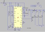
Note: At present diagram there is no load connected at the outputs but there will be 15V load in series to 3ohm resistor.
 

Hi,

Read through some forum threads about SMPS problems.
--> then you will see: the most likely problems are
* bad PCB layout
* choosing non suitable parts (inductor, capacitor...)

And thus it's the same here as with many other threads:
We need to see
* your exact and complete schematic (not the datasheet one)
* your PCB layout
* your exact partnames, manufacturers and datasheet (-links)

Klaus
 

Your circuit doesn't consider this datasheet hint:

If the application does not require the use of the EXTVCC LDO (the EXTVCC pin is grounded), the REGSD feature must be defeated with a pull-up resistor between SS and INTVCC.
 

Hi,

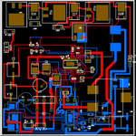
I have made the exact PCB based on the schematic given in the datasheet with minor changes in resistors to adjust the input and output as per my requirement. Apart from this have used two IC circuits instead of one, so I can get two different output from each of the ICs. Here i have attached the whole schematic of my design and I would even like to know if the p channel mosfet used for the reverse polarity is fine or not.

Thank you.
circuitdesign.JPG 1st IC.PNG2nd IC.pngBOM.PNGpcb.png
 

Hi,

The problem is the PCB layout. It is not suitable to get reliable and stable operation of the LT3895.
It's almost impossible to do "switching power" applications without solid GND plane.
You urgently need to follow the PCB layout considerations in the datasheet.
Just "connecting" nodes like in the schematic doesn't work.

Klaus

- - - Updated - - -

Added:

I just checked the paths of some important signals on your PCB.
It's absolutely unsuitable.
It seems you just let an autorouter make some connections.
But an autorouter doesn't know about the signal waveforms and which signal carries which current.

I'm sorry to say this: I see no chance to make the circuit running with this PCB layout.
You first need to learn how to layout "critcal signal paths".
Designing a PCB layout for an LT3895 is not a simple task. It may be a challenge even for an experienced electronics technician.

Please start with more simple circuits.

Klaus
 

I agree about possible Layout problems as discussed by KlausSt. But as a matter of fact, circuits not considering the REGSD feature will run neither. I recently tried on the DC2117 eval board.
 

Thank you guys for your valuable suggestions. I made the required changes as said you and it worked well upto certain voltages. Further testing is still going on.

Apart from this I would like to know how can I give a short circuit protection to my load using the IC configuration?.

If that's not possible then what will be the alternative way to provide the short circuit protection to load which need output voltage at 19.8V and total current should not exceed 3 amps.

At present, when I short the output to the ground the current drawn is way high then expected.
 

Hi,

Apart from this I would like to know how can I give a short circuit protection to my load using the IC configuration?.
--> Just read the datasheet.
Every PDF Reader should have a search function...

Klaus
 

Status
Not open for further replies.

Similar threads

Part and Inventory Search

Welcome to EDABoard.com

Sponsor

Back
Top