Continue to Site

Welcome to EDAboard.com

Welcome to our site! EDAboard.com is an international Electronics Discussion Forum focused on EDA software, circuits, schematics, books, theory, papers, asic, pld, 8051, DSP, Network, RF, Analog Design, PCB, Service Manuals... and a whole lot more! To participate you need to register. Registration is free. Click here to register now.

[Moved]: Loop stablity of TIA

Status
Not open for further replies.

chenximing4305

Newbie level 5
Joined
Feb 13, 2018
Messages
9
Helped
0
Reputation
0
Reaction score
0
Trophy points
1
Activity points
49
HI,
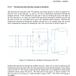
i study the thesis as attached file,and has a question.in page 65,the testbench for loop stablity of TIA.i cann't undenstand how does it work.

312.png

View attachment eetop.cn_DESIGN OF LNA and MIXER FOR MULTI-BAND WCDMA (1).pdfView attachment eetop.cn_DESIGN OF LNA and MIXER FOR MULTI-BAND WCDMA (1).pdf
 

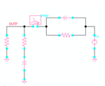
To measure the loop gain of the TIA, the outer feedback loops have to be broken - and by this the feedforward transmission, too. This is accomplished by the 2 IPROBEs iprobe-symbol.png which are transparent for DC (resistance=0), but show infinite impedance for ac frequencies.
 

314.png

i doubt why the author duplicate the forward feedback loop,he add a iprobe at OUTP,OUTN,i cann't find which loopgain to be simulated.
why not add the iprobe at the output of TIA directly?
 

i doubt why the author duplicate the forward feedback loop
Because it is a fully differential TIA, isn't it?

why not add the iprobe at the output of TIA directly?
Because loops should be broken preferably in front of a high impedance node (MOSFET gate input). This wouldn't be the case at the output.
 

Status
Not open for further replies.

Similar threads

Part and Inventory Search

Welcome to EDABoard.com

Sponsor

Back
Top