neazoi
Advanced Member level 6
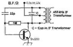
Hi, I need a schematic for a low voltage (1.5 to 3v) 455KHz ceramic resonator BFO.
I cannot find one on the net. any help is appreciated.
This worked for me https://www.eleccircuit.com/low-volts-crystal-frequency-generator-circuit/ but not for ceramic resonators
I cannot find one on the net. any help is appreciated.
This worked for me https://www.eleccircuit.com/low-volts-crystal-frequency-generator-circuit/ but not for ceramic resonators
Last edited: