Continue to Site

Welcome to EDAboard.com

Welcome to our site! EDAboard.com is an international Electronics Discussion Forum focused on EDA software, circuits, schematics, books, theory, papers, asic, pld, 8051, DSP, Network, RF, Analog Design, PCB, Service Manuals... and a whole lot more! To participate you need to register. Registration is free. Click here to register now.

Welding machine (need circuit explain)

Status
Not open for further replies.

LefTux

Newbie
Joined
Oct 29, 2017
Messages
4
Helped
0
Reputation
0
Reaction score
0
Trophy points
1
Activity points
34
Hello, i would like, if anybody know, to help me to understand the circuit of inverter welding machine. There are to points.
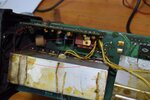
1. On the following picture i have marked on red cycle a ultra fast diode near to mosfets. What is the rule of this?
1.JPG

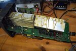
2. On the following picture i have marked on red cycle a group of 6pcs BYV52 diodes. What is the rule of these?
2.JPG

Thanks.
 

Attachments

  • 2.jpg
    2.jpg
    492.8 KB · Views: 94
  • 1.jpg
    1.jpg
    517.4 KB · Views: 95

It is hard to say without a schematic diagram.

In any case, the first picture seems to be a recovery diode, the diode that dissipates the energy accumulated into the lekage inductance of the trafo.
The other BYV52 diodes could be the rectifiers to allow the welding machine to work in DC mode on the output.

Mandi
 

In any case, the first picture seems to be a recovery diode, the diode that dissipates the energy accumulated into the lekage inductance of the trafo.

Mandi

Thank you very much. I have not schematic. I understand about the BYV52, but not about the above diode (SITTA 1206 DI). There are not trafo.
 

Status
Not open for further replies.

Similar threads

Part and Inventory Search

Welcome to EDABoard.com

Sponsor

Back
Top