Continue to Site

Welcome to EDAboard.com

Welcome to our site! EDAboard.com is an international Electronics Discussion Forum focused on EDA software, circuits, schematics, books, theory, papers, asic, pld, 8051, DSP, Network, RF, Analog Design, PCB, Service Manuals... and a whole lot more! To participate you need to register. Registration is free. Click here to register now.

Ground Problem cause SPI to fail

Status
Not open for further replies.

kappa_am

Full Member level 6
Joined
Jul 16, 2012
Messages
331
Helped
19
Reputation
38
Reaction score
19
Trophy points
1,298
Location
Vancouver
Activity points
3,859
Hi All,
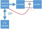
I have designed a power electronic inverter. the DC link is supplied by single phase grid by a diode bridge. The control section is supplied by an isolated DC link. The problem is that when I connect negative bus of the DC link to the GND (isolated from the grid) of the control board's power supply, the SPI communication between the control board and IO board is failed. Following block diagram shows the whole system.
**broken link removed**

I measured the voltage of the mid of the DC link with respect to control board's power supply; it is like below picture:
**broken link removed**

When I connect the negative bus of the DC link to the GND of the control board, at the beginning, there is a small spark but not considerable current flows ( I have 100mA fuse in the path).

When I disconnect the rectifier from the grid ( DC link is still charged) the midpoint voltage becomes flat zero (as it should be). The midpoint sway when the rectifier's diodes are conducting.

I wonder where is the problem? What is the solution? what about connecting a capacitor between system ground and GND of control section's power supply?

Furthermore, two of my microcontroller programmers failed in a month ( after several programming). I think it may be because of this ground problem.

I would be greatly thankful if you help me with this problem and share your comments.
 

Hi Brad,
Please find the attachments in the given order below:

Drawing1.jpg

photo_2018-03-09_21-42-34.jpg
 

Practically all "isolated" supplies have some capacitance to earth (often a 10nF Y capacitor), meaning they are not truly isolated at high frequencies. If you connect your controller to a node with a large offset from earth (like a non-isolated DC link) then you may get a large surge through that capacitance, easily enough to kill the IO of a microcontroller or whatever.

One potential solution is to ensure that when connecting the controller, the connection between the controller ground and the DC link is made before any other nodes. That will allow the surge to pass harmlessly (maybe) through gnd before the other signals make contact. You could also add clamping circuits to the sensitive signals. Or just avoid hot-plugging the controller.
 

Thank you for your response.
I have no problem with IO board and control board even when their supply's GND is connected to the negative rail of DC link. The problem is that the SPI fails when the negative rails connection occurs, and I lose programmers (connected to grid's GND via USB and PC) through time ( in a month or so). Really strange situation. The problem is that in healthy conndition two negative rails are not connected. this is a warning situation. I do not want to turn OFF the circuit in this situation; just want to issue a warning. What can I do?
 

There should be isolation between DC link and the controllers USB interface, but it's not shown in your block diagram.
 

Hi FvM,
Yes, the DC sources used to supply IO, control board and drivers are isolated from the grid. The utilized IGBT drivers have isolated DC/DC converter inside. So yes the system negative rail is isolated respect to USB's GND which is connected to grid GND. What is the cause of gradually failing programmer? is some thing wrong why does not die at first time get connected? this problem aside, why midpoint of the DC link which should be at the same potential of grid GND sway as I showed above?
 

Yes, the DC sources used to supply IO, control board and drivers are isolated from the grid.
But the isolation is cancelled by the red line in post #3?

Is it so that the SPI failure occurs with active PWM or already in idle state? I won't be surprised in the former case, because the ground short injects strong common mode interferences into the control circuit.

midpoint of the DC link which should be at the same potential of grid GND
Unlikely. What's the connected grids earthing type? https://en.wikipedia.org/wiki/Earthing_system
 

Thank you for your response.
I have no problem with IO board and control board even when their supply's GND is connected to the negative rail of DC link. The problem is that the SPI fails when the negative rails connection occurs, and I lose programmers (connected to grid's GND via USB and PC) through time ( in a month or so).
So you have no problem when connecting the two gnds... except that you do have problems....

And now you mention that you are connecting USB programmers to the control board. This almost certainly defeats the isolation, unless the programmer is isolated. In that case, it's not surprising that you are breaking programmers, maybe even your computer eventually...
 

I think I cannot convey my meaning.

control board's supply is isolated and connecting its negative rail to the grid's ground and USB does not cause a problem, theoretically and practically. The situation that the negative rail of the DC link shorted to the control board supply's negative rail is a situation that may happen in working period (while inverter is working, no programmer is connected), this situation also is not dangerous and may not cause a problem because of isolated supply of the control board and IGBT drivers. However, I want to issue a warning alarm. my problem is kinda strange because SPI fails and programmer fails after a month or even more (more than 200-300 times of programming). there is a problem that I don't know about, but I understand that shorting negative rail of DC link to USB definitely will kill PC and other circuits (it is not the problem). I would be grateful if you share any other comment.

Thank you all for your time.
 

I think I cannot convey my meaning.

control board's supply is isolated and connecting its negative rail to the grid's ground and USB does not cause a problem, theoretically and practically.
What is "the grid's ground"? You mean earth potential?
The situation that the negative rail of the DC link shorted to the control board supply's negative rail is a situation that may happen in working period (while inverter is working, no programmer is connected), this situation also is not dangerous and may not cause a problem because of isolated supply of the control board and IGBT drivers.
To clarify, you are getting "failures" in this configuration (no USB programmer connected)? What do you mean by fail? Do components get damaged, or is the SPI communication just not happening correctly?

However, I want to issue a warning alarm. my problem is kinda strange because SPI fails and programmer fails after a month or even more (more than 200-300 times of programming). there is a problem that I don't know about, but I understand that shorting negative rail of DC link to USB definitely will kill PC and other circuits (it is not the problem). I would be grateful if you share any other comment.
Again, what do you mean by "fail" with regards to the programmer. And under what conditions is the programmer connected to the system? Your diagram doesn't show this.
 

Yes, my meaning from grid ground is earth potential.

every time I connect the negative rail of the DC link to the negative rail of the control board SPI communication is failed (although I am using chip selection line, a few bits are shifted). No component is damaged. In this situation, the programmer is not connected.

in the second situation, DC link is charged, negative rail of DC link and the negative rail of the control board are isolated. I connect the programmer, I am able to program to debug etc, but after several programming and debugging the programmer is damaged (almost after a month or so). If something wrong why it doesn't damage in the first time that got connected to board? ( I never connect the programmer to the circuit when the DC link's negative rail and control board's negative rail are connected to each other)
 

You didn't yet answer the question in post #8 about operation conditions during SPI failure.

Regarding programmer failure, connecting the programmer to a system with floating ground discharges common mode voltage to the programmer during connecting.
 

HI FvM,
Sorry, I was checking with earthing type. The earthing type is TN-S, and yes the PWM is active when the GNDs connection occurs, however, I disable PWMs after detecting that GNDs are shorted. I think so, the problem may be high common mode voltage. what is the solution?
 

The observed failure pattern (shifted SPI bits) suggests PWM switching noise injected into the SPI signals, particularly SCK.

In my view it's an everyday problem in power electronic design. Can be a problem of circuit layout, insufficient common mode filtering, unsuitable digital isolators or line drivers, inappropriate grounding.
 

Thanks for the response, I don't think it is PWM noises. I had that one and solved it. when the inverter is working I don't have any problem with SPI. the only case that SPI gets screwed up is when the control board supply's negative rail gets shorted to DC link's negative rail. It is because of common voltage exist in this faulty situation. How can I keep SPI working even with this high common mode voltage?

Thanks
 

I'm not sure what you specifically mean with high common voltage in this situation. Obviously there should be no DC voltage difference between the grounds of both SPI bus peers.
 

I mean when I connect negative rail of control board's power source (which also supplies IO board) to the negative rail of the DC link, it voltage goes half of a DC link voltage negative compared to grid's GND. In this situation, SPI between IO and control board fails. IO and control boards' negative rail is common.
 

Yes, but a constant DC common mode voltage shouldn't cause any problems, provided you have sufficient isolation.
 

Looking to picture posted on Post #3, could you please explain to me why when power rectifier's diodes conduct, the midpoint voltage of the DC link varies respect to the negative rail of control board's power supply while DC link voltage is constant? I guess that one or some isolation ICs (gate driver, etc) have not enough reinforced isolation or their isolation is damaged. isn't it?
 

Status
Not open for further replies.

Similar threads

Part and Inventory Search

Welcome to EDABoard.com

Sponsor

Back
Top