Continue to Site

Welcome to EDAboard.com

Welcome to our site! EDAboard.com is an international Electronics Discussion Forum focused on EDA software, circuits, schematics, books, theory, papers, asic, pld, 8051, DSP, Network, RF, Analog Design, PCB, Service Manuals... and a whole lot more! To participate you need to register. Registration is free. Click here to register now.

Micro controller digital(inp/output) protection

Status
Not open for further replies.

Nihaludeen

Member level 2
Joined
Oct 29, 2017
Messages
46
Helped
0
Reputation
0
Reaction score
0
Trophy points
6
Activity points
460
I am using Arduino as my controller, I want to protect the digital pin of controller before giving it to the circuit. And I am using the digital pin as output.
Is diode clamp is good solution for it?
And after I connect the diode clamp circuit to the arduino's output, the controller's stucks .
Any solution for protection oupur pins of controller.
I have attached the image below.
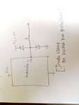
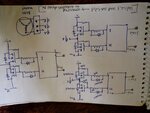
Diode clamp cicruit.jpg main circuit..jpg
 

you have included input protection configuration for an output pin.

what is the output device you want to drive with protection?

the image does not have the connecting point of output.

what problem you encounter when you connect the diode and resistor combination in output pin ?
 

Hi,

"Protect" ...

There is no simple protection against all extremes.

First you need to define "against what" you want to protect the pin.
* continous short circuit against GND (or any lower voltage)
* continous short circuit against VCC (or any higher voltage)
* ESD? It usually is difined as: a capacitance, it's charge_voltage and the series_resistance. Maybe the repeat rate.

Against ESD:
A very good protection is:
Pin -- series resistance -- two diodes -- capacitor to GND.
How it works.
The capacitance will slow down the extremely fast ESD pulse. (100p may be sufficient)
The diodes will limit the voltage, but (because of the high current peaks) usually this voltage is beyond the microcontroller specification.
Thus you need the series resistor to keep the current within specified values.

An additional series resistor (at the ESD side) may be useful for high power "surge pulses" to dissipate the energy.
A further big (transil, transzorb) diode may be useful for even higher energy pulses.

Klaus

Thank you for response friends.
Sry I forgot to say from what I want to protect.
I am trying to make a 3 phase inverter . And I am using Arduino as a controller, and I want to protect my output pin from reverse voltage or current.
 

Hi,

and I want to protect my output pin from reverse voltage or current.
A 3 phase inverter needs halfbridges with MOSFETs or IGBTs....and they need gate driver circuits.
This gate driver circuits generate no reverse voltage or reverse current.

Klaus
 

Status
Not open for further replies.

Similar threads

Part and Inventory Search

Welcome to EDABoard.com

Sponsor

Back
Top