orangeseyler
Newbie
Hi.
I am working on a 8x2 patch array and I have some problems creating the proper feed network.
The frequency is 9.4 GHz, I use Rogers RO4003 (dielectric constant 3.55) with 0.508 mm (20 mil) thickness and 35 μm copper cladding.
I have a lot of results, so I will attach a lot of pictures and ask a lot of questions, but any help would be appreciated")
First I tried to create a 2x2 array similar to that shown on figure 1, so I can create something similar like shown on figure 2.
I designed a single patch first (results on figure 3) then a 2 element array (results on figure 4).
Then here comes the problem. When I created a 2x2 array, I had no space to get the feed line to the midpoint (see figure 5). I put a coax feed there and simulated it to get the results, but I need to create 4 of these 2x2 arrays and feed them with microstrip lines, so I need some solution for that.
I saw 2 possible solutions for this problem (figure 6), but I don't really find the details about them. I tried to do the first one, but I don't know how should I bend those lines? I bent it in 45 degree and joined the lines together, but the results are bad even for 2 element array (figure 7). I guess something is wrong with the bending of the lines. I can make 90 degree bendings with good results, but this 45 degree bending produces very bad results.
And what is the second solution? I assume I should feed the pairs of the patches with different phases because they are in opposite direction. But why is that? And what is the phase difference?
I also saw a 8x2 array created in a different way which is shown on figure 8, but I don't understand where is the feed for that array? I created a 8 element array (results on figure 9) for that purpose, but how do I proceed?
Thanks for any help.
I am working on a 8x2 patch array and I have some problems creating the proper feed network.
The frequency is 9.4 GHz, I use Rogers RO4003 (dielectric constant 3.55) with 0.508 mm (20 mil) thickness and 35 μm copper cladding.
I have a lot of results, so I will attach a lot of pictures and ask a lot of questions, but any help would be appreciated
First I tried to create a 2x2 array similar to that shown on figure 1, so I can create something similar like shown on figure 2.
I designed a single patch first (results on figure 3) then a 2 element array (results on figure 4).
Then here comes the problem. When I created a 2x2 array, I had no space to get the feed line to the midpoint (see figure 5). I put a coax feed there and simulated it to get the results, but I need to create 4 of these 2x2 arrays and feed them with microstrip lines, so I need some solution for that.
I saw 2 possible solutions for this problem (figure 6), but I don't really find the details about them. I tried to do the first one, but I don't know how should I bend those lines? I bent it in 45 degree and joined the lines together, but the results are bad even for 2 element array (figure 7). I guess something is wrong with the bending of the lines. I can make 90 degree bendings with good results, but this 45 degree bending produces very bad results.
And what is the second solution? I assume I should feed the pairs of the patches with different phases because they are in opposite direction. But why is that? And what is the phase difference?
I also saw a 8x2 array created in a different way which is shown on figure 8, but I don't understand where is the feed for that array? I created a 8 element array (results on figure 9) for that purpose, but how do I proceed?
Thanks for any help.
Attachments
-
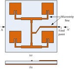 fig1 - 2x2 array.jpeg111.5 KB · Views: 101
 -
 fig2.png5.2 KB · Views: 93
 -
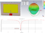 fig3 - patch results.png194.1 KB · Views: 99
 -
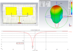 fig4 - 2 element array results.png122.3 KB · Views: 88
 -
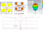 fig5 - 2x2 array results.png154.6 KB · Views: 103
 -
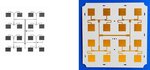 fig6.jpg40 KB · Views: 99
 -
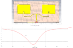 fig7.png33.2 KB · Views: 97
 -
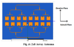 fig8.png58.7 KB · Views: 103
 -
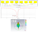 fig9 - 8 element array.png140.4 KB · Views: 102