Continue to Site

Welcome to EDAboard.com

Welcome to our site! EDAboard.com is an international Electronics Discussion Forum focused on EDA software, circuits, schematics, books, theory, papers, asic, pld, 8051, DSP, Network, RF, Analog Design, PCB, Service Manuals... and a whole lot more! To participate you need to register. Registration is free. Click here to register now.

Gate current of Switched Capacitor DC-DC Converter

Status
Not open for further replies.

JEOvergaard

Junior Member level 1
Joined
Jan 6, 2018
Messages
16
Helped
0
Reputation
0
Reaction score
0
Trophy points
1
Activity points
190
Dear all

I am currently designing a switched capacitor 40 V -> 20 V DC-DC converter in a 180 nm process. During this, I have encountered some issues with estimating the average current needed by my gate-drivers of the MOSFETs.

Math:

I have estimated the gate capacitance to 4.9 nF by a DC analysis of the circuit. Furthermore we are switching at 200 kHz.
This amounts to average:

I_avg = Qg * fsw = 980 uA


Simulation:

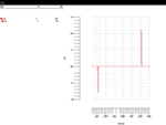
In the simulation I have made a transient plot of the gate-current waveform, used the calculator function average() to assess the average current. The result is however only 11 uA though, which is far from the expected value.

The following figure shows a whole switching cycle for the gate-current, for which the math function has been used.
Ig.png


Best regards Jacob
 

Average current is not what you want. Driving the FET
gate takes current from VDD and later dumps it to VSS.
Average at the driver output ought to be zero (-ish) as
the current reverses. Try looking at the supply current,
or the high side leg of the driver totem-pole.
 

I see a value of Igate = 1.1 A from your plots.

Please check your units for current.
 

Thank you for answering dick_freebird

My issue is, that I currently drive the MOSFETs with ideal gate-drives. This means I have a voltage source connected directly from G-S on my NMOS. Do you know of any to deal with that?

I am trying to do this calculation in order to estimate the requirements of my floating power supplies.
 

The units are in fact ampere, and not milli or micro. But this large spike happens due to my ideal/fast switching of the MOSFET. But nevertheless, I should be able to get an average of the current.

Even though the average in reality should equal to around 0, due to the charge-second balancing.
 

To serve a useful purpose, averaging would be performed over turn-on and turn-off phase separately, not a full cycle. Hope you see why.

My issue is, that I currently drive the MOSFETs with ideal gate-drives. This means I have a voltage source connected directly from G-S on my NMOS. Do you know of any to deal with that?
What are you particularly asking here? Gate driver must be designed to generate at least the required Vgs to turn the transistor fully on and off but not exceed the maximum ratings. With your high voltage levels, there's no way to avoid a kind of bootstrap driver or floating Vgs clamp circuit. Providing suffcient gate current can be an issue in IC design.
 

To serve a useful purpose, averaging would be performed over turn-on and turn-off phase separately, not a full cycle. Hope you see why.

Giving the average current in a capacitor must be zero, it does make sense. But I fail to understand why calculating the average current with the fomula: I_avg = Qgate * fsw does not equal zero.

What are you particularly asking here? Gate driver must be designed to generate at least the required Vgs to turn the transistor fully on and off but not exceed the maximum ratings. With your high voltage levels, there's no way to avoid a kind of bootstrap driver or floating Vgs clamp circuit. Providing suffcient gate current can be an issue in IC design.

I was given an excellent idea by looking into the upper leg of my totem-pole driving the MOSFET to investigate the actual average current. My question was as how to assess the average current without the totem-pole, since I am driving the MOSFETs ideally for the moment.

I do know, that there is no way around boot-strapping, charge pumps or whatever solution is chosen, but in the beginning the circuit design is idealized as much as possible, in order to get a functional switched capacitor converter. Next part is the gate-drive with floating supplies and lastly a level-shifter.
 

But I fail to understand why calculating the average current with the fomula: I_avg = Qgate * fsw does not equal zero.
Depends on which Qgate you drop into the formula. There are Qg,on and Qg,off, obviously with opposite sign. Summing up both gives zero charge and zero average gate current.
 

My question was as how to assess the average current without the totem-pole, since I am driving the MOSFETs ideally for the moment
Look only at the half period, already described in post #6.
 

Status
Not open for further replies.

Part and Inventory Search

Welcome to EDABoard.com

Sponsor

Back
Top