Continue to Site

Welcome to EDAboard.com

Welcome to our site! EDAboard.com is an international Electronics Discussion Forum focused on EDA software, circuits, schematics, books, theory, papers, asic, pld, 8051, DSP, Network, RF, Analog Design, PCB, Service Manuals... and a whole lot more! To participate you need to register. Registration is free. Click here to register now.

Noise of Driving relay from avr

Status
Not open for further replies.

mshh

Full Member level 6
Joined
May 30, 2010
Messages
349
Helped
0
Reputation
0
Reaction score
0
Trophy points
1,296
Location
usa
Activity points
3,871
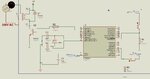
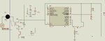
My avr drives relay to switch ac lamp ,i use ciruit like the attached. the same output is used for ac motor
There is external interrupt on int 0 ,When i connect the ac supply of loads the avr enters interrupt, and the lcd hangs and shows nothing.
I used capacitor 1uf on the +5 supply of the circuit. all the dc supply of control circuit and relay circuit is common. all the ground is common.
 

Attachments

  • ttt.jpg
    ttt.jpg
    78.6 KB · Views: 124
Last edited:

All the ground may be "common", but what does it look like physically? If you've got the return current from your relay running through the same copper that the processor is on, that could be your problem. As an experiment, if it's not too difficult, I would suggest you lift the ground side of the relay and run a wire directly to the power supply ground. Also, it's possible transients are getting in through the +5V side of the supply, which you don't show. This really could just be a layout problem. It could also be that a transient is sneaking into the reset line.
 

the relay takes its supply from the avr supply point,but both the relay ground and avr ground meet in point then go to the ground of the supply as shown in figure attached
 

Attachments

  • tfg.jpg
    tfg.jpg
    80 KB · Views: 129

Hi,

Most probably it's not the circuit (schematic) that causes the problem, but the PCB layout /wiring.

So post a picture or photo of your circuit where we can see all the power paths, the signal paths and all their return paths.

Klaus
 

here is my pcb
 

Attachments

  • inr.pdf
    53.6 KB · Views: 110

All the relay current flows through a long track, passing between AVR pins. The layout is your problem!

Try cutting the long track between the cathode of D3/Relay and the LCD then wiring D3/Relay directly to the output of C3 (which appears to be a regulator).
You should also have a decoupling capacitor wired across the AVR supply and ground pins as close to the pins as possible.
The crystal loading capacitors also need to be returned tho the AVR ground as closely as possible, the long tracks you are using are too inductive and also carry current from other parts of the circuit. Try to keep the oscillator wiring as short as you can and independent of other circuits.

The board bears little resemblance to the schematic!

Brian.
 

Hi,

Safety first:
You say the relay switches 220V AC ... but there is about no creepage distance beween dangerous voltage and low voltage nodes.
This violates safety rules dramatically. Dont hurt/kill yourself or others!
I recommend at least 6mm of clearance. Exact values can de found in the safety regulations of your country and depends on a lot of parameters, like humidity, dirt, casing...

Don't use this PCB to switch dangerously high voltages!!

I even doubt that your relays are certified for those high voltages.

****

I agree with Brian.

My opinion:
Nowadays you need a solid GND plane. No copper fill.
For sure it may work without..but regarding EMI, EMC, lower signal voltages, higher signal frequencies, high speed switching (power) signals...you may expect malfunction.

Some connections seem to generate short circuits. For example the coil signals of K2 ..

Klaus

- - - Updated - - -

Hi,

there are a lot of mistakes in your layout:
* S1 connection is wrong. It does essentially nothing.
* All your LEDS won´t work
* LS1 and LS2 are connected in parralled, this makes no sense to me.
* No input capacitor at the voltage regualtor.
* IC2 seems to be a dual OPAMP where one OPAMP input has floating inputs.
* I assume the buzzer won´t work
* ... and so on.

Why don´t you use a free schematic & PCB layout software ... that "connects" schematic and layout?
Then they automatically inform you about layout errors like: shorted signals, distance problems, missing routed signals, ....

Then first draw the complete schematic.
* do the placement (with the help of the schematic)
* generate the GND_Plane on the bottom side
* do the signal wiring as much as possible at the top side.
* do the unavoidable routing at the bottom. Make the traces short to keep GND plane solid. Placement: Take care of GND currents..

Klaus
 

would the interface of push button to PINd.3 destroy it as there is no resistor to limit the current.
 

Attachments

  • tfg.jpg
    tfg.jpg
    80 KB · Views: 106

Presume PD3 (as well as PC6) is configured as input pin. Why do you expect excessive current into an input?
 

as we connect limiting resistor on output. Is it harmful to connect 5v directly to the input PD3?
 
Last edited:

Hi,

If I want to know the input current of a pin when 5V is connected, then I look into the datasheet:
Look for I_IH.
The first "I" is for current
the second "I" is for input
The "H" is for "HIGH" level.

You should find the specification somewhere in the "Electrical characteristics" section.
Maybe "I/O characteristics", maybe "DC characteristics"..I´m sure you find it.
If you don´t find I_IH, then most probably it is IIH or similar. Maybe there is a chart for input current vs input voltage.

If you found the value...can you decide on your own if this current is harmful or not?

Klaus
 

the same output is used for ac motor

In addition to what has been already noted of issues in your circuit/layout, it is also important to be aware of the term "ac motor", which although technically refers mainly to the brushless type, there is another type of motor, the universal one (with brushes) that is compatible with AC power voltages, but this kind is a real headache, being able to induce spikes even in a design with a more robust layout than yours. In other words, making a test with lamp do not ensure it will work with the intended load.


should i connect the ground of the dc circuit with the neutral of ac circuit

If you do not intend to kill yourself, absolutely NOT.
Both are different references, for distinct purposes.
 

Hi,

You refer to a triac control.
The triac is controlled with the signal on the gate ... which refers to the A1 pin of the triac.
The A1 pin of the triac carries the load currrent and thus it needs to be connected with mains.

It is a professional not isolated application. Usually completely installed in an isolating plasic box with no user accassable devices like - in your case - a pusbutton and LCD.
Applications are: Remote controlled dimmer, heating regulation, fan control...

The problem is that it seems you don't have the knowledge about safety regulations.
Worst is that I've warned you already about this and you seem to ignore this completely.
I know you don't like to read this:
I don't want to be responsible if you hurt/kill yourself or someone else... thus I recommend
* stop your project here
* don't connect your circuit to dangerous voltage
* learn about safety regulations (this is not a task of a couple of days)
* then redesign your circuit

I will respond to questions about safety ... but stop to respond to other technical/functional questions.

Be careful.

Klaus
 

he connected one terminal of ac supply to the ground of MCU
In addition to Klaus's remarks, note that the citted circuit is implemented within a known simulator environment, therefore it does not pose a risk of death to anyone. Note that TRIAC control is one of the most diffused designs for hobbists along the World and you will find from the most safe to the most dangerous being selt in the stores of cheap products. Solely using a bare plastic knob is not a suitable measure.

Moreover, there is a "mistake" in the circuit, think about: Why one would use an opto-coupler when is sharing the same ground reference among power and control sections? The plausible answer is that in many cases, when trying to simulate different ground references in SPICE-based simulators, an error arises (floating node, if I remember correctly) which the author of this publication may not have been able to solve - adding a very high resistor between GND and Neutral would solve. In shorts, don't connect Neutral and circuit Ground together.
 

i designed new pcb with your recommendations, i need your opinions please (noise-protection)
 

Attachments

  • Doc1.pdf
    754.9 KB · Views: 91

Status
Not open for further replies.

Similar threads

Part and Inventory Search

Welcome to EDABoard.com

Sponsor

Back
Top