Continue to Site

Welcome to EDAboard.com

Welcome to our site! EDAboard.com is an international Electronics Discussion Forum focused on EDA software, circuits, schematics, books, theory, papers, asic, pld, 8051, DSP, Network, RF, Analog Design, PCB, Service Manuals... and a whole lot more! To participate you need to register. Registration is free. Click here to register now.

constant current source

Status
Not open for further replies.

brownt

Member level 3
Joined
Sep 25, 2017
Messages
63
Helped
0
Reputation
0
Reaction score
0
Trophy points
6
Activity points
597
assuming a 5 volt supply across a 10K ohm potentiometer, how can i make it so there is a variable 5 volts with a constant current of about 15mA?
 

Linear voltage regulators maintain a constant output voltage for a given range of input voltage (variable input voltage). If output voltage is constant, then output current will be constant.
 

Linear voltage regulators maintain a constant output voltage for a given range of input voltage (variable input voltage). If output voltage is constant, then output current will be constant.

I see. I only have 5 volts available. how much of that would be lost across a low voltage drop out regulator.

Is there any other solution?
 

how much of that would be lost across a low voltage drop out regulator.
Low.. depends on the regulator of course. 50 mV maybe if it is a MOS type ?
 

Hi,

is a variable 5 volts
What does this mean? Either it is 5V OR it is variable.
What range?

You know how to use Ohm´s law?
Then you can calculate which resistance you need to get 15mA at 5V. This is far away from 10k. Thus you are very close at one end of the potentiometer.
If you shift it a bit further to the end, then most likely the current is high enough to burn the potentiometer.

****
To me it´s not clear what you want to achieve. A piece of paper and a pencil could give useful information.

Klaus

- - - Updated - - -

Added:

Low.. depends on the regulator of course. 50 mV maybe if it is a MOS type ?
If you go close to the limit, then the regulator has no headroom to regulate for fluctuations.

Klaus
 

Low.. depends on the regulator of course. 50 mV maybe if it is a MOS type ?
hmm actually, thinking about it, the 5 volts 'is' coming from a regulator, but i guess as the wiper is moved the resistance changes and so too does the current. When the wiper is at the top there will be 5 volts, but no current limiting and so I guess things will burn. When the wiper is getting toward the bottom there is very little current (5 / 10K).

I can put a current limiting resistor in, say 330 ohms and so when the wiper is at the top there will be 5 volts at 15mA, but when the wiper is down the bottom there will be very little current still.

- - - Updated - - -

I have 5 volts, and want to make it variable from 0 - 5 volts, using a 10K ohm potentiometer.

flucuations I think would not be an issue for this not exacting application.
 

Hi,

Really have to say, Bourns have some interesting app notes/booklets on using potentiometers/trimpots, and one aspect is using a resistor from V+ to the potentiometer, and thereby attempting to keep the wiper around the middle for reasons of safety, hate to go on, but trimpots are allegedly a bit feeble used as you intent to - if they go short, what stops a short-circuit straight to ground? That's why it's good practice to put the resistor.

All I can suggest is, I've also wanted to make the circuit fit the components from time to time, but it doesn't work. Even just a trimpot at the lowest end will have a small voltage across it so some of the 5V will be lost, all the same. Maybe using a step-up converter or a decent way of paralleling MOSFETs and putting the outputs in series or something?
 

If you only need 15ma, then connecting the pot output to a rail-rail op amp configured as a follower may work for you.
For example, look at the (relatively) high output current LM7321 single or LM7322 dual op amps.
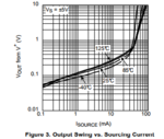
As show below from the data sheet, the output drop at maximum output will be about 0.3V below 5V with a 15mA load.
At lower output voltages (and/or current), the output will match the pot voltage.

Capture.PNG

- - - Updated - - -

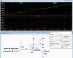
Here's an LTspice simulation of the circuit using the LM7322 with a pot rotation from 0 to 1 (0% to 100%).
It shows a 120mV difference between the input and output at the 5V pot setting with a 333 ohm resistive load drawing 15mA @ 5V out.
At lower voltages the output follows the pot voltage within a few mV offset.

Capture.PNG

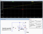
Here's the simulation with a constant-current 15mA load.
The results are essentially the same.

Capture1.PNG
 
Last edited:

Hi,

Really have to say, Bourns have some interesting app notes/booklets on using potentiometers/trimpots, and one aspect is using a resistor from V+ to the potentiometer, and thereby attempting to keep the wiper around the middle for reasons of safety, hate to go on, but trimpots are allegedly a bit feeble used as you intent to - if they go short, what stops a short-circuit straight to ground? That's why it's good practice to put the resistor.

All I can suggest is, I've also wanted to make the circuit fit the components from time to time, but it doesn't work. Even just a trimpot at the lowest end will have a small voltage across it so some of the 5V will be lost, all the same. Maybe using a step-up converter or a decent way of paralleling MOSFETs and putting the outputs in series or something?


Thanks all. Good suggestions. Turns out the load on the wiper is only about 70microamps, and so a series resistor with the top of the pot is all that is needed.
 

Status
Not open for further replies.

Part and Inventory Search

Welcome to EDABoard.com

Sponsor

Back
Top