ljille
Member level 2
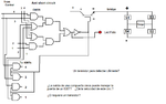
I'm trying to do an inverter based on Sine Pulse Width Modulation (SPWM). I did two stages, control and power. The first, done with AmpOp 741 and comparators LM311 generates 4 signals wich would be injected on the gates of a bridge of IGBTs (G4PC50K IR 022P), these receive a DC signal to be modulated by them. The power schematic is attached. View attachment IRG4PC50.PDF
I made a record of the signals out of the control circuit and used the data in excel. The result is that the signal es zero during certain time, then describes a sinuidal figure on positive side, wich is the expected signal. They are not in phase with the oposite branch, so it doesn't go to short circuit, so I suppose they are right.
Anyway, the first test was to feed just the power stage, with 110 V to the bridge rectifier wich would feed the IGBTs with a rippled DC (it has not a capacitor yet), but, with the IGBTs off (no signal in the gate), I supposed no current would pass trhough. So I would have just a rectified signal feeding IGBTs and nothing out. But the result instead was a slpike and that the IGBTs 2 and 3 was burned.
The first option I think is that the IGBTs do conduct without a signal in their gate (on air), so if they are not connected to ground, they will conduct, so they go on short circuit inmediatly.
The second option is that I have something wrong in the design, but I don't see it. (see schematic)
The design is quite simple, and I have checked the circuit several times so there are not short circuits between traces and obviously that heat sinkers are correctly isolated.
Indeed the first spike was a trace, so I thought could have been a fault on isolation (traces too near), so I fixed it and then the IGBTs were blowed.
The third option, as other thread says, could be the absence of the capacitor on the rectifier (wich I thought would give us a rippled signal but DC at least), wich could bring an overvoltage situation on the IGBTs caused by inductance, although it would remain anyway the question about if the IGBT conducts with the gate 'on air'. It is not clear to me what capacitance is right for this circuit. I was thinking on a microwave capacitor, of 1 uF 2000 V.
I have to know what happened and solve it before replacing any component, so please, if somebody knows it, I'll be very grateful with your advice.
When it be resolved, I have a further question about the capacity of a SPWM inversor or inverter to drive an induction universal motor, and if it's velocity can be varied with a third stage circuit based on a triac with zero passing detection circuit, although the frequency of the control (10 KHz) be higher than what can drive the moc3021 and the Triac itself. That is, if it can drive velocity between 80 to 100% although it 'jumps' steps of the spwm.

Thank you for your time
Luis Jiménez I.

- - - Updated - - -
Note that it has no charge at all, it is an open circuit in this sense.
- - - Updated - - -
Note that it has no charge at all, it is an open circuit in this sense.
I made a record of the signals out of the control circuit and used the data in excel. The result is that the signal es zero during certain time, then describes a sinuidal figure on positive side, wich is the expected signal. They are not in phase with the oposite branch, so it doesn't go to short circuit, so I suppose they are right.
Anyway, the first test was to feed just the power stage, with 110 V to the bridge rectifier wich would feed the IGBTs with a rippled DC (it has not a capacitor yet), but, with the IGBTs off (no signal in the gate), I supposed no current would pass trhough. So I would have just a rectified signal feeding IGBTs and nothing out. But the result instead was a slpike and that the IGBTs 2 and 3 was burned.
The first option I think is that the IGBTs do conduct without a signal in their gate (on air), so if they are not connected to ground, they will conduct, so they go on short circuit inmediatly.
The second option is that I have something wrong in the design, but I don't see it. (see schematic)
The design is quite simple, and I have checked the circuit several times so there are not short circuits between traces and obviously that heat sinkers are correctly isolated.
Indeed the first spike was a trace, so I thought could have been a fault on isolation (traces too near), so I fixed it and then the IGBTs were blowed.
The third option, as other thread says, could be the absence of the capacitor on the rectifier (wich I thought would give us a rippled signal but DC at least), wich could bring an overvoltage situation on the IGBTs caused by inductance, although it would remain anyway the question about if the IGBT conducts with the gate 'on air'. It is not clear to me what capacitance is right for this circuit. I was thinking on a microwave capacitor, of 1 uF 2000 V.
I have to know what happened and solve it before replacing any component, so please, if somebody knows it, I'll be very grateful with your advice.
When it be resolved, I have a further question about the capacity of a SPWM inversor or inverter to drive an induction universal motor, and if it's velocity can be varied with a third stage circuit based on a triac with zero passing detection circuit, although the frequency of the control (10 KHz) be higher than what can drive the moc3021 and the Triac itself. That is, if it can drive velocity between 80 to 100% although it 'jumps' steps of the spwm.
Thank you for your time
Luis Jiménez I.
- - - Updated - - -
Note that it has no charge at all, it is an open circuit in this sense.
- - - Updated - - -
Note that it has no charge at all, it is an open circuit in this sense.