Continue to Site

Welcome to EDAboard.com

Welcome to our site! EDAboard.com is an international Electronics Discussion Forum focused on EDA software, circuits, schematics, books, theory, papers, asic, pld, 8051, DSP, Network, RF, Analog Design, PCB, Service Manuals... and a whole lot more! To participate you need to register. Registration is free. Click here to register now.

Three stage amplifier

Status
Not open for further replies.

promach

Advanced Member level 4
Joined
Feb 22, 2016
Messages
1,199
Helped
2
Reputation
4
Reaction score
5
Trophy points
1,318
Activity points
11,636
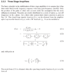
As in section 2.2.3 of View attachment phd_jramos.pdf , I have few questions:

1) Why assume "third order Butterworth frequency response with unity gain frequency" ?

2) Why negative DC feedback ?

3) How do we obtain expression (2.2) from (2.1) ?

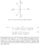
4) How do we obtain the expression of open loop undamped natural frequency response, ωno as (sqrt(2) * ωc)?

5) Could anyone elaborate more on "a peaking around 10 % of the final value will be found in the closed loop transient response due to the phase margin value." ?
Screenshot from 2018-02-18 00-48-44.png

Screenshot from 2018-02-18 00-49-05.png
 
Last edited:

If we use 1st stage amplifier then poles are located as s=+/-1 which is corresponds to an unstable system. Similarly if we use 2nd stage amplifier there would 4 solution i.e. four pole at 45, 135, 225, 315 degree. no poles at 0 and 180 degree.
so if we use 3rd stage amplifier it is better suited to our needs, especially if we use the angle 0, +60 and -60 degree.
 
poles are located as s=+/-1 which is corresponds to an unstable system

Why would poles at 0 and 180 degree lead to unstable system ?
 

As in section 2.2.3 of View attachment 144690 , I have few questions:

1) Why assume "third order Butterworth frequency response with unity gain frequency" ?

Choice for zero peaking response (Butterworth) needs adequate GBW for pole selected. Otherwise there will be peaking, so the assumption may be false. (later he says 10% due to phase margin is the evidence of this false assumption. My tools tell me

1st stage (n=1) Q=0.5 must have GBW=50x breakpoint and
2nd stage (n=2) Q=1 then GBW=100x breakpoint to get
net (n=3 order) Q = 1⁄√2

... use Butterworth for flattest passband frequency response) but is underdamped Q = ​1⁄√2.)
- choose Bessel for maximally flat group delay, since Q is lower. 0.5, 0.69 still needs GBW = 100x breakpoint as 2 decades still has phase shift below breakpoint of open loop.


2) Why negative DC feedback ?

see https://en.wikipedia.org/wiki/Butterworth_filter#Transfer_function .


3) How do we obtain expression (2.2) from (2.1) ?

see above again... poorly defined

4) How do we obtain the expression of open loop undamped natural frequency response, ωno as (sqrt(2) * ωc)?


5) Could anyone elaborate more on "a peaking around 10 % of the final value will be found in the closed loop transient response due to the phase margin value." ?


I think it is due to inadequate open loop GBW
 
Last edited:

Reply from thesis author:

1) You do not have to, but Butterworth polynomials are well known and the fact that it generates flat frequency response is convenient.

2) I do not understand your question. What is exactly that you are asking? In any case, I suggest you to read a good book on control theory.

3) Equation (2.1) is a general form for closed loop systems with feedback fdc and gain Go. Similarly, equation (2.2) is a general equation for a third order Butterworth filter.

4) Any control book will show you how, if you make equation (2.5) equal to equation (2.6).

5) If you take equation (2.5) and plug it into equation (2.1), and the derive the inverse Laplace transform to obtain the step response, you will see the peaking. The Butterworth approach guarantees flat response in the frequency domain but it is silent on what happens in the time domain. You can play with poles location to see the impact on the time domain step response. And if you then look at Figure 3.7, it now becomes obvious why amplifiers having very similar bode plot can have such different step responses.
 

Status
Not open for further replies.

Similar threads

Part and Inventory Search

Welcome to EDABoard.com

Sponsor

Back
Top