Continue to Site

Welcome to EDAboard.com

Welcome to our site! EDAboard.com is an international Electronics Discussion Forum focused on EDA software, circuits, schematics, books, theory, papers, asic, pld, 8051, DSP, Network, RF, Analog Design, PCB, Service Manuals... and a whole lot more! To participate you need to register. Registration is free. Click here to register now.

DC voltage divider using capacitors

Status
Not open for further replies.

prateek3790

Full Member level 2
Joined
Feb 8, 2016
Messages
131
Helped
1
Reputation
2
Reaction score
1
Trophy points
18
Activity points
1,190
Hi All,

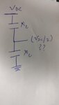
Is it possible to make a voltage divider using capacitor for a dc source. I want to use this as a voltage reference and not for sourcing current(no load is applied to this).
From my understanding if two similar caps are being used then at the middle the voltage will be half of the applied voltage.(Vdc*Xc/2*Xc). I used ltspice and similar beavious was seen.(used skip initial condition option)

however during one of the discussion someone told untill unless there is some leckage in the circuit capacitors can not be used as a dc voltage didvider, In other words i can not derive a voltage using capacitive divider.

So little confused whether it's possible to get a dc voltage divider using cap.
 

Attachments

  • IMG_20180217_183447.jpg
    IMG_20180217_183447.jpg
    395.4 KB · Views: 139

They can be used. Switched capacitor converters are an application of this...
 

Hi,

capacitors block DC, thus it won´t work.

Your simulation shows theoretical values for a short time. And with defined (= ideally discharged) capacitors.
If you want to simulate real conditions, then you mee to tell this to the simulator.
Please note: "DC" is infinite in time.

* You won´t find capacitors with high precision capacitance.
* you won´t find capacitors with no leakage current
* you can´t design a PCB with no leakage current.
* and you won´t have a "load" with zero input current.

Klaus

ok. so can we say that potential at that point will be zero.i mean how the voltage on the caps will look like. for top cap the upper plate will be at Vdc and the bottom cap the lower plate will be at zero. the point where both cap have a common point what will b potential there? can i get that in simulation as well.
 

As already said, there is no way to avoid leakages, then the two caps divider will works only in an ideal world.

However the DC losses of a capacitor are very low, usually lower than any load you can connect. This means that at the connection point the voltage will be almost always zero, if the load is referred to ground.

The order of the insulation resistance (that is the equivalent resistor placed in parallel to the capacitor to represent its leakage) is 100 to 10^7 Mohms for ceramics capacitors (depending from dielectric) and 0.1 to 10 Mohm in case of Al or Ta electrolytics as you can find in "http://www.kemet.com/Lists/TechnicalArticles/Attachments/6/What%20is%20a%20Capacitor.pdf"
 

Hi,

As said...the simulation is partly correct..
If you have two discharged capacitors of equal capacitance in series, one side grounded
...and now you connect them to VCC, then you will see VCC/2 at the middle.

But this is
* for a short time only....the voltage will change with time
* and this is a "switched" voltage .... which is the opposite of DC voltage.

For sure you can build a "circuit", a with some switches and a control unit ... to get half of the input voltage.
But there is no "DC" at the capacitors anymore...and it is a lot more complex than the two capacitors of post#1.

Klaus
 

Add to this that any reference to "switched capacitors" is actually turning the situation from a DC to a type of AC, though possibly with a strange waveform.
Take it further - any time-varying feature would involve capacitor charging and discharging - so not DC.

Real capacitors may well have "some" leakage, but maybe as high as several Giga-Ohms, and the real possibly that more will leak across a bit of old fingerprint reacting with humidity than gets through the dielectric insulation. A true capacitor having finite conductors and physical size will show some inductance also. There will be a self-resonant frequency, and maybe another for a series mode equivalent. Model it fully, and a capacitor is a little L C R network.

To get instant precision voltage division for DC, you need the Real part of the component impedance to be there - the RESISTIVE part.
Apply AC, and resistors STILL give you a division - and it is still an AC version keeping up with the applied AC.

With only pure capacitors there, you can have precision voltage division only with AC. It uses the REACTIVE part of the component impedance.

We won't bother right now to go too deep into complex numbers way of expressing impedance, but think [REAL PART resistive ] + j*[REACTIVE PART capacitive ]
The reactive part for a capacitor depends on frequency. Look it up to find Xc=1/j*(2*pi()*Frequency*Capacitance),and the "j" down there ends up giving it a minus sign.

The lower the frequency, the bigger Xc it gets, until at ZERO frequency, we have arrived at DC, and the impedance is infinite!
(Except for the few electrons that leak over the old fingerprint, or find their way through the insulation)!

Good capacitors holding DC might discharge more from incoming cosmic radiation than from insulation leak, but you find that some circuits that involve extremely high impedances (like pH meters) might use PCB boards made of glass, or alumina, or ceramic loaded PTFE, and amplifier inputs surrounded by grounded "guard rings". This is where one starts thinking of currents as a few tens of million electrons instead of microamps!

Good to remember is that reactive components (capacitors and inductors) are only there temporarily while things are CHANGING! They truly disappear once a steady state (DC) is reached. They re-appear again the instant you try to change (discharge), and of course, AC is a case of "continuously changing".
 

Status
Not open for further replies.

Part and Inventory Search

Welcome to EDABoard.com

Sponsor

Back
Top