flote21
Advanced Member level 1
Hello folks!
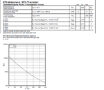
I need to design a conditioning circuit for a NTC with the attached datasheet:

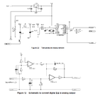
The manufacturer recommend the next conditioning circuit based on a sigma-delta modulator:

It is important to comment that I need to convert the digital output of the sigma-delta modulator into analog values. It is a design requirement. Therefore a DSP in a FPGA o uC of the sigma-delta modulator ouptur is not allowed.
I tried to simulate the attached conditioning circuits with LTSpice, but I was not able to get the Spice model of the Sigma-Delta modulator part. So my questions are:
1) How to emulate in the output of the sigma-delta simulator with LTSpice if not any spice model of that part is available?
2) Is there any other ideas to conditioning the NTC temperature signal with the same accuracy than the sigm-delta conditioning circuit?
Thanks in advance to everyone.
I need to design a conditioning circuit for a NTC with the attached datasheet:

The manufacturer recommend the next conditioning circuit based on a sigma-delta modulator:

It is important to comment that I need to convert the digital output of the sigma-delta modulator into analog values. It is a design requirement. Therefore a DSP in a FPGA o uC of the sigma-delta modulator ouptur is not allowed.
I tried to simulate the attached conditioning circuits with LTSpice, but I was not able to get the Spice model of the Sigma-Delta modulator part. So my questions are:
1) How to emulate in the output of the sigma-delta simulator with LTSpice if not any spice model of that part is available?
2) Is there any other ideas to conditioning the NTC temperature signal with the same accuracy than the sigm-delta conditioning circuit?
Thanks in advance to everyone.