Continue to Site

Welcome to EDAboard.com

Welcome to our site! EDAboard.com is an international Electronics Discussion Forum focused on EDA software, circuits, schematics, books, theory, papers, asic, pld, 8051, DSP, Network, RF, Analog Design, PCB, Service Manuals... and a whole lot more! To participate you need to register. Registration is free. Click here to register now.

keypad function to return 0 to 16 characters

Status
Not open for further replies.

vead

Full Member level 5
Joined
Nov 27, 2011
Messages
285
Helped
3
Reputation
6
Reaction score
3
Trophy points
1,298
Location
india
Activity points
3,815
Hello

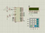
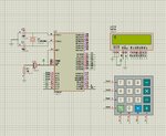
I need to display characters on screen using matrix keypad. if i press key on keypad characters should be display on the screen. I wrote code to print characters on screen using keypad but when I press any key program is not showing anything on the screen.

I think there is problem in my keypad function. I am trying to figure out what's wrong in keypad function. Is it correct way to read keypad or I need batter function then this function

This code is only for keypad

Code:
 /* Processor: AT89C51 */
 /* Compiler:  Keil for 8051*/
 /* LCD 16*2  and keypad 4*4 */
 
#include <reg51.h>

#define Port P0                //keypad connected to port P0

#define C1  P1^0 
#define C2  P0^1
#define C3  P0^2 
#define C4  P0^3  


 char get_key()
 {
	unsigned char i, k, key=0;

	k = 1;

	for( i = 0; i < 4; i++)          //loop for 4 rows
	{		

		keyport &=~ (0x80 >> i);	//to make rows low 1 by 1

     		       if(!C1)	                 //check if key1 is pressed
			{
				key = k+0;	        //set key number
				while(!C1);      	//wait for release
				return key;     	//return key number
			}

			if(!C2)	                //check if key2 is pressed
			{   
				key = k+1;	         //set key number
				while(!C2);	         //wait for release
				return key;	         //return key number
			}

			if(!C3)	                 //check if key3 is pressed
			{
				key = k+2;	         //set key number
				while(!C3);	         //wait for release
				return key;     	 //return key number
			}

			if(!C4)                  	//check if key4 is pressed
			{
				key = k+3;	        //set key number
				while(!C4);	        //wait for release
				return key;	        //return key number
			}

		k = k + 4;			        //next row key number

		keyport |= 0x80 >> i;    	//make the row high again
	}

	return 0;			            //return 0 if no key pressed
}

 
 void main()
 {
  unsigned char keypress; 
	
	 Port =0xff;     	//all keypad pins high 
	 while(1)
	 {

		keypress=get_key();

   		if(keypress)	
			 Lcd_Data(keypress);
	 }
	 
 }
 
Last edited:

Hi,

Without schematic....hard to say.

But with a quick view...
* I see no debouncing software (this is not the source of your problem)
* and I see no "wait" for the signals to settle (usually this is needed with a matrix keypad)

Klaus
 

A couple of questions about the code. In the defines, C0 is defined as P1^0,. should this be P0^0 ?.
In main, PORT is set to all 1"s. In function get_key, keyport is used, I don't see this variable declared or defined. Is it "PORT" ?
 

Hi,

It seems you tried to write the code without prior
* schematic
* signal flow chart
* timing diagram.

Additionally it seems you tried to write the code as a whole...without dividing it into smaller pieces that can be verified individually.

Sooner or later you will find out that there is a good reason why professionals use the above methods.

Klaus
 

Hi,

Without schematic....hard to say.

But with a quick view...
* I see no debouncing software (this is not the source of your problem)
* and I see no "wait" for the signals to settle (usually this is needed with a matrix keypad)

Additionally it seems you tried to write the code as a whole...without dividing it into smaller pieces that can be verified individually.

Klaus

I have connected matrix keypad 4*4 to port P0 of 8051 and Lcd to port P1 of 8051. I have issues with keypad function only

I have divide code into pieces that's why I am trying to write only keypad routine

A couple of questions about the code. In the defines, C0 is defined as P1^0,. should this be P0^0 ?.
In main, PORT is set to all 1"s. In function get_key, keyport is used, I don't see this variable declared or defined. Is it "PORT" ?

My mistake sorry
Code:
#include <reg51.h>

#define keyport P0                //keypad connected to port P0

#define C1  P0^0 
#define C2  P0^1
#define C3  P0^2 
#define C4  P0^3  


 char get_key()
 {
	unsigned char i, k, key=0;

	k = 1;

	for( i = 0; i < 4; i++)          //loop for 4 rows
	{		
        
		keyport &=~ (0x80 >> i);	//to make rows low 1 by 1

     		       if(!C1)	                 //check if key1 is pressed
			{
				key = k+0;	        //set key number
				while(!C1);      	//wait for release
				return key;     	//return key number
			}

			if(!C2)	                //check if key2 is pressed
			{   
				key = k+1;	         //set key number
				while(!C2);	         //wait for release
				return key;	         //return key number
			}

			if(!C3)	                 //check if key3 is pressed
			{
				key = k+2;	         //set key number
				while(!C3);	         //wait for release
				return key;     	 //return key number
			}

			if(!C4)                  	//check if key4 is pressed
			{
				key = k+3;	        //set key number
				while(!C4);	        //wait for release
				return key;	        //return key number
			}

		k = k + 4;			        //next row key number

		keyport |= 0x80 >> i;    	//make the row high again
	}

	return 0;			            //return 0 if no key pressed
}

 
 void main()
 {
  unsigned char keypress; 
	
	 keyport =0xff;     	//all keypad pins high 
	 while(1)
	 {

		keypress=get_key();

   		if(keypress)	
		Lcd_Data(keypress);
	 }
	 
 }
 

PORT 0 of 89C51 is open collector. Are there pull up resistors wired to pull PORT 0 hIgh ?
 

PORT 0 of 89C51 is open collector. Are there pull up resistors wired to pull PORT 0 hIgh ?

Please look at the attached picture
 

Attachments

  • keypad.jpg
    keypad.jpg
    173 KB · Views: 159

Hi,

are you sure R1, C3 connection is correct?

Klaus
 

Hi,

are you sure R1, C3 connection is correct?

Klaus

I am sure connection is correct. I searched on internet for keypad function. it's look correct
 

Hi,

I am sure connection is correct. I searched on internet for keypad function. it's look correct
R1, C3 have nothing to do with keypad. I doubt that you connected it correctly. Give link to where you found the circuit.

Klaus
 

Hi,

in the link ... R1/C3 is used to control the RESET function. It generates a delay to enable the power supply to stabilize before the microcontroller starts to operate.

..But not in your design.

In opposite to the link schematic your RESET is connected to VCC directely. If you modify the design you should be aware of what you do.
I don´t know if your circuit is correct for your microcontroller. Please consult the datasheet.


Klaus
 

In opposite to the link schematic your RESET is connected to VCC directely. If you modify the design you should be aware of what you do.
I don´t know if your circuit is correct for your microcontroller.

I don't think there is any problem in design because design work with given code in link

I think I just need to make good keypad function
 

Attachments

  • keypad2.jpg
    keypad2.jpg
    166.8 KB · Views: 143

In addition to the schematic showing incorrect reset wiring, it does not agree with the code you posted above. The schematic shows the keypad on port 1 instead of port 0 shown in the code, and shows
the LCD on port 3 instead of port 1. Is this really the schematic for your circuit ?
 

In addition to the schematic showing incorrect reset wiring, it does not agree with the code you posted above. The schematic shows the keypad on port 1 instead of port 0 shown in the code, and shows
the LCD on port 3 instead of port 1. Is this really the schematic for your circuit ?
The code I posted was just an example. if you read post#1 there you can see I am having problem with function not port. if you are saying to connect keypad to port P1. i will connect where you will say to connect.

Now the main problem for me is keypad routine.
 

Hi,

The code I posted was just an example.
This is like bringing my neighbour´s car to the garage when my car fails.
It´s annoying when one tries to help .. but one can not rely on the given informations. Neither schematic, nor code.
I leave this thread.

Klaus
 

Hi,


This is like bringing my neighbour´s car to the garage when my car fails.
It´s annoying when one tries to help .. but one can not rely on the given informations. Neither schematic, nor code.
I leave this thread.

Klaus

What's the wrong ? I wanted to make function that can return number so I just did google and found the some example. I checked that design that was working fine with the code given in link so I thought design is okay but there is fault in my program. then I wrote routine for keypad. I asked is this a better way to read the keypad. My question was, what would be a good keypad routine in c.
 
  • Like
Reactions: rberek

    rberek

    Points: 2
    Helpful Answer Positive Rating
What's the wrong ? I wanted to make function that can return number so I just did google and found the some example. I checked that design that was working fine with the code given in link so I thought design is okay but there is fault in my program. then I wrote routine for keypad. I asked is this a better way to read the keypad. My question was, what would be a good keypad routine in c.

The 8051 family microcontroller has P0,1,2,3 Ports with slightly different circuitry, so if you do not provide accurate information, indicating what is connected to where, no one can assess whether your problem lies in hardware or firmware scope.
 

The 8051 family microcontroller has P0,1,2,3 Ports with slightly different circuitry, so if you do not provide accurate information, indicating what is connected to where, no one can assess whether your problem lies in hardware or firmware scope.

It would be much appreciate if you will help me with connection because I don't have deep understanding of 8051 architecture. I did google but I did't get which port is suitable for keypad interfacing.
 

I don't know the 8051 architecture at all but I have also mad a couple of Google searches and the information is there. (The one I found was **broken link removed** but there are certainly many more.)
In your schematic, you show that the LCD is connected to Port #2. That port has internal pull-up resistors on the pin and so that should be OK.
That leaves Port 0, 1 and 3. Port 3 has a number of alternate functions associated with it which can be useful (UART, interrupt etc.) so we can leave that for now.
Port 0 can be used for both data and address and requires pull-up resistors so that will add a bit of complexity to your circuit.
However Port 1 also has internal pull-up resistors and is only used as an IO port - sounds perfect for your purposes.
Although you drive the top 4 bits of the port, the bottom 4 bits will be pulled low when a key is pressed that is connected to one of the column lines that is also being driven low by your code.
Now to your code. People have been telling you that you cannot separate your code from the hardware but you seem to have been ignoring this. Here is why it is important.
When the mechanical parts of a keypad switch join (on pressing the key) or open (releasing the key) the contact is not instantaneous and continuous. There is a thing called 'contact bounce' (https://www.elexp.com/Images/Contact_bounce_and_De-Bouncing.pdf is one of very many documents explaining this) that can last for a number of milliseconds. This means that you code, which can execute hundreds of instructions in a millisecond) will see each opening and closing during the bounce period.
If you use a simple 'if' statement to see when the key is pressed, you might see the first of the bounces and then continue. You then have a 'while' to wait until the keypress is released, but this will probably see then end of the bounce you have just detected and so let the program continue. Even though you then return from your function to try to display something, you code can work fast enough that you will call your keypress function again in time to pick up a subsequent bounce - still from the same key press. It might take seconds for you to press the key once, but your code will see 10's or perhaps 100's of presses from the contact bounce.
I don't know what the 'Lcd_Data' function does but if it just displays the character in the next position, then it will full up the display with characters every time you pre
Therefore you must take this into account. You can add circuitry to suppress the bounces but you can also do the debouncing in software. The choice is yours.
You have also not really told us what the problem is that you are having other than nothing appears on the LCD which you have immediately assumed is a fault with the keypad function. In your code (at least the code you have shown) you do not seem to have initialised the LCD. What you have shown in the schematic appears to be a standard HD44780 interface device. These must be send the appropriate initialisation sequence before they will start up.
Another reason nothing will show is that you have not set up the contrast correctly. If it is too low then nothing will show. If it is too high then all you get is a rectangle of dots. What you want is to set the contrast to just when the rectangle of dots disappears so that when a character is shown, it will be displayed.
Finally, the code returned from your keypress function will be a number between 0 (no keypress) and 16. The values from 1 to 16 are then passed directly to the 'Lcd_Data' function. Unless that does some translation of the number to a character code, then the LCD will probably ignore it as invalid data or display it as a space.
My advice is to get one thing running at a time. Perhaps start with the LCD and make sure that it is actually displaying some characters. Then add in a single button press (with debounce) to understand how that works. Then work up to the keypad.
Susan
 
  • Like
Reactions: vead

    vead

    Points: 2
    Helpful Answer Positive Rating
Status
Not open for further replies.

Part and Inventory Search

Welcome to EDABoard.com

Sponsor

Back
Top