Continue to Site

Welcome to EDAboard.com

Welcome to our site! EDAboard.com is an international Electronics Discussion Forum focused on EDA software, circuits, schematics, books, theory, papers, asic, pld, 8051, DSP, Network, RF, Analog Design, PCB, Service Manuals... and a whole lot more! To participate you need to register. Registration is free. Click here to register now.

Feedback amplifier circuit redrawing

Status
Not open for further replies.

bznm

Newbie level 3
Joined
Feb 11, 2018
Messages
3
Helped
0
Reputation
0
Reaction score
0
Trophy points
1
Activity points
30
Given the following circuit,

bcM56.jpg

I need to redraw it as a Series Shunt feedback amplifier, i.e. with the following topology:
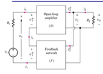
Y4niB.png

Identifying the AC equivalent circuit seems to be easy: 12V and -12V become GND and current generator turns into an open circuit. However I have troubles identifying the amplifier net and the feedback net and the series shunt topology. Could you help me redrawing the circuit?
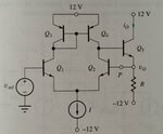
 

The output is vo.
The feedback is node P.

You should be able to figure out the rest from that
 
  • Like
Reactions: bznm

    bznm

    Points: 2
    Helpful Answer Positive Rating
The output is vo.
The feedback is node P.

You should be able to figure out the rest from that
Thanks for the answer!
However I am not able to understand it... Feedback net should be a two port network.. and I can't see what are these ports.
Unfortunately my textbook (and I didn't have any luck searching on other books) doesn't cover the details about identifying the topology.

Thanks again for the help
 

.......... Feedback net should be a two port network.. and I can't see what are these ports.
Unfortunately my textbook (and I didn't have any luck searching on other books) doesn't cover the details about identifying the topology.
In the general case, a feedback net can have two ports but it doesn't have to be (and most feedback networks don't).
It this case the second port is the common (ground) connection.
 

In the general case, a feedback net can have two ports but it doesn't have to be (and most feedback networks don't).
It this case the second port is the common (ground) connection.
I suppose that the feedback box contains Q5, while Q1,Q2,Q3,Q4 are the amplifier box, because the signal is input in Q1, isn't it?
 

No - Q5 is part of the main amplifier, because the output vo is located at the emitter of Q5.
 

Status
Not open for further replies.

Similar threads

Part and Inventory Search

Welcome to EDABoard.com

Sponsor

Back
Top