razer6
Newbie level 3
Hi,
I am using the MMMC-flow of Cadence Innovus. Hereby, I set the IO placement file and then initialize the design using the command init_design.
My IO file looks like the following:
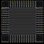
This places the IO and corner pads. For the corner pads however, the assigned offset value is not respected and they are placed directly on the edge of the previous IO pad.
You can see that in the following screenshot.

I can modify the placement of the corner pad in the GUI, but this should work after init_design.
Can someone help me how to get the corner pads being placed with the same pitch as the IO pads and respect the offset value of the IO file?
Thank you!
Best regards,
Robert
I am using the MMMC-flow of Cadence Innovus. Hereby, I set the IO placement file and then initialize the design using the command init_design.
My IO file looks like the following:
Code:
(globals
    version = 3
    io_order = default
)

(iopad
  (topleft
    (inst name="PADS/CORNER_NW"  offset=1200 )
  )

### left side (W, bottom to top)
  (left
    (inst name="PADS/PAD_gndcore0"   offset= 120 )
    (inst name="PADS/PAD_APB_PAddr_DI[3]"   offset= 210 ) 1
    (inst name="PADS/PAD_APB_PAddr_DI[2]"   offset= 300 ) 0
    (inst name="PADS/PAD_APB_PAddr_DI[1]"   offset= 390 )
    (inst name="PADS/PAD_APB_PAddr_DI[0]"  offset= 480 )
    (inst name="PADS/PAD_APB_PSlverr_SO"  offset= 570 )
    (inst name="PADS/PAD_APB_PReady_SO"  offset= 660)
    (inst name="PADS/PAD_APB_PWrite_SI"  offset= 750 ) # 5
    (inst name="PADS/PAD_APB_PSel_SI"  offset= 840 )
    (inst name="PADS/PAD_APB_Penable_SI"  offset= 930 )
    (inst name="PADS/PAD_Resetn_SI"  offset= 1020 )
    (inst name="PADS/PAD_Clk_CI"  offset=1110 )
  )
  (bottomleft
    (inst name="PADS/CORNER_SW"     offset=0.00)
  )
### bottom side (S, left to right)
  (bottom
    (inst name="PADS/PAD_APB_PWdata_DI[2]"  offset= 120 )
    (inst name="PADS/PAD_APB_PWdata_DI[1]"  offset= 210 )
    (inst name="PADS/PAD_APB_PWdata_DI[0]"  offset= 300 )
    (inst name="PADS/PAD_APB_PAddr_DI[4]"   offset= 390 )
    (inst name="PADS/PAD_APB_PWdata_DI[3]"  offset= 480 )
    (inst name="PADS/PAD_APB_PWdata_DI[4]"  offset= 570 )
    (inst name="PADS/PAD_APB_PWdata_DI[5]"  offset= 660)
    (inst name="PADS/PAD_APB_PWdata_DI[6]"  offset= 750 )
    (inst name="PADS/PAD_APB_PWdata_DI[7]"  offset= 840 )
    (inst name="PADS/PAD_APB_PWdata_DI[8]"  offset= 930 )
    (inst name="PADS/PAD_APB_PWdata_DI[9]"  offset= 1020 )
    (inst name="PADS/PAD_vddcore0"  offset=1110 )
  )
  (bottomright
    (inst name="PADS/CORNER_SE" offset=0.00)
  )
### right side (E, bottom to top)
  (right
    (inst name="PADS/PAD_APB_PWdata_DI[10]"  offset= 120 )
    (inst name="PADS/PAD_APB_PWdata_DI[11]"  offset= 210 )
    (inst name="PADS/PAD_APB_PWdata_DI[12]"  offset= 300 )
    (inst name="PADS/PAD_APB_PWdata_DI[13]"  offset= 390 )
    (inst name="PADS/PAD_APB_PWdata_DI[14]"  offset= 480 )
    (inst name="PADS/PAD_APB_PWdata_DI[15]"  offset= 570 )
    (inst name="PADS/PAD_APB_PRdata_DO[0]"  offset= 660)
    (inst name="PADS/PAD_APB_PRdata_DO[1]"  offset= 750 )
    (inst name="PADS/PAD_APB_PRdata_DO[2]"  offset= 840 )
    (inst name="PADS/PAD_APB_PRdata_DO[3]"  offset= 930 )
    (inst name="PADS/PAD_APB_PRdata_DO[4]"  offset= 1020 )
    (inst name="PADS/PAD_gndio0"   offset= 1110 )
  )
### top side (N, left to right)
  (topright
    (inst name="PADS/CORNER_NE"  offset=1200)
  )
  (top
    (inst name="PADS/PAD_APB_PRdata_DO[5]"  offset= 120 )
    (inst name="PADS/PAD_APB_PRdata_DO[6]"  offset= 210 )
    (inst name="PADS/PAD_APB_PRdata_DO[7]"  offset= 300 )
    (inst name="PADS/PAD_APB_PRdata_DO[8]"  offset= 390 )
    (inst name="PADS/PAD_APB_PRdata_DO[9]"  offset= 480 )
    (inst name="PADS/PAD_APB_PRdata_DO[10]"  offset= 570 )
    (inst name="PADS/PAD_APB_PRdata_DO[11]"  offset= 660)
    (inst name="PADS/PAD_APB_PRdata_DO[12]"  offset= 750 )
    (inst name="PADS/PAD_APB_PRdata_DO[13]"  offset= 840 )
    (inst name="PADS/PAD_APB_PRdata_DO[14]"  offset= 930 )
    (inst name="PADS/PAD_APB_PRdata_DO[15]"  offset= 1020 )
    (inst name="PADS/PAD_vddio0"   offset= 1110 )
  )
)
This places the IO and corner pads. For the corner pads however, the assigned offset value is not respected and they are placed directly on the edge of the previous IO pad.
You can see that in the following screenshot.

I can modify the placement of the corner pad in the GUI, but this should work after init_design.
Can someone help me how to get the corner pads being placed with the same pitch as the IO pads and respect the offset value of the IO file?
Thank you!
Best regards,
Robert