Continue to Site

Welcome to EDAboard.com

Welcome to our site! EDAboard.com is an international Electronics Discussion Forum focused on EDA software, circuits, schematics, books, theory, papers, asic, pld, 8051, DSP, Network, RF, Analog Design, PCB, Service Manuals... and a whole lot more! To participate you need to register. Registration is free. Click here to register now.

Fly back LTspice simulation

Status
Not open for further replies.

satiz

Member level 5
Joined
Jun 9, 2013
Messages
87
Helped
3
Reputation
6
Reaction score
3
Trophy points
1,288
Activity points
1,999
Hi,

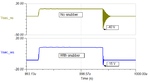
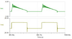
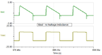
I am planning to simulate flyback design in LTspice, but the output is not coming as expected. Please help me to solve this.
Actual Smps design as per the PI expert
5A.png
LTspice
ltspice7v.png

Thanks in advance
 

Simplify the circuit down to the lowest parts count.
* Feed it a DC supply.
* Disconnect the DCR snubbing network (for the time being).
* Attach a lone resist or to the secondary.

After adjusting everything properly, you should see the secondary produce current only during the second half of the cycle when no current is in the primary.

Later you can add the snubber, the output components, etc.
 

Hi,

it's working now... Wrong value entered in primary inductance. After correcting it's working.
I have one more doubt, why my output is having spike kind of thing.

Attached is simulation output

output.png
 

why my output is having spike kind of thing.
That is the output across the output cap ? It might be because you are using a non ideal, high ESR,ESL electrolytic cap. You need ceramic cap in parallel with the output cap.

Why are you driving M1 with 30 V ?
 

We call it oscillation rather than "spike". To see how it's brought up, inspect more circuit voltages and currents.

You see heavy oscillating flyback current, probably unrealistic high leakage inductance.
There are some hidden component parameters, e.g. output capacitor ESR. You apparently have some 10 mOhm ESR.

Besides too high gate driver voltage (would damage a real MOSFET), you have two circuit faults:
- ground connection of input voltage is shorting a rectifier
- DCR diode has insufficient voltage rating
 

Agree, your waveform looks more like what I would expect from the secondary current shape, with some ringing caused by leakage inductance resonating with primary device/diode capacitance.

You can also see the effect of snubbing over the rectifier diode.
 

Attachments

  • rect_snub.png
    rect_snub.png
    12.4 KB · Views: 193
  • sec_I.png
    sec_I.png
    11.2 KB · Views: 175
  • sec_I_ideal.png
    sec_I_ideal.png
    11.5 KB · Views: 144

Status
Not open for further replies.

Similar threads

Part and Inventory Search

Welcome to EDABoard.com

Sponsor

Back
Top