Continue to Site

Welcome to EDAboard.com

Welcome to our site! EDAboard.com is an international Electronics Discussion Forum focused on EDA software, circuits, schematics, books, theory, papers, asic, pld, 8051, DSP, Network, RF, Analog Design, PCB, Service Manuals... and a whole lot more! To participate you need to register. Registration is free. Click here to register now.

What are the limitations of switching power supply to enhance it's frequency?

Status
Not open for further replies.

sunrise264

Newbie level 5
Joined
Jan 31, 2018
Messages
8
Helped
0
Reputation
0
Reaction score
0
Trophy points
1
Activity points
134
There is a paper entitled the working principle of high-power adjustable switching power supply and mentioned a new design of high-power adjustable switching power supply which using Buck-type switching power supply topology, with a single PWM output, MC33060 as a control IC, and dual output IR2110 driver chip and then designed a high-voltage high-power switching power supply as an effective solution to adjustable high-voltage switching power supply circuit, which can solve the problem effectively that in the non-isolated topology, the common switching power supply can not reach high limits, and attached with over-current protection usage.
But my question is what about medium and small power devices? What is the bottleneck for medium and small power devices to increase their frequencies of switching power supply?
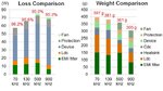
In the premise of meeting the efficiency of design requirements, we may blame the main power loss on switch and transformer, another book about switching power supply design mentioned the switching loss is mainly divided into switching on & off loss, charging/ discharging loss, gate-drive losses and so on. Because of the gate charge and discharge loss is not small, what if we use the technique of softswitch to get a ZVS one, which is also called zero voltage switching?
Compared to the current kind of switches, the gate charge and discharge losses are actually not significant considering meeting the voltage and current stress of other Losses, and transformer losses could also be better solved finely coupled by the primary and secondary sides, or using planar cores to reduce losses. In summary, currently, let’s say fly-back 500kHz's, it is difficult to pursue, what are the bottlenecks to making the fly-back 500kHz's ?
 

Interesting questions, but I don't see how the linked paper should be related to it. Using simple hysteretic 33060 as pwm controller reveals just ignorance. The suggested circuit may at best serve as an educational lab setup, although I fear it's rather misleading than instructive. Just ignore the volt and ampere numbers in the table.

I agree that 500 kHz at high voltage is only feasible with soft switching techniques, so you need to study the circuit topologies that enable it. I don't see that planar transformers reduce losses in the first place, you can be happy if you keep the efficiency of a carefully designed conventional transformer. But they promise compact and economic switchers, design for manufacturability.
 

A few comments:

-ZVS may be a necessary way to get high voltage + high frequency but typically ZVS is tricky to achieve over a full operating range. That's doubly true for a supply that needs to widely vary output voltage, as you mention above.

-For example an LLC topology can realistically achieve ZVS over a widely varying load but isn't good if it has to widely vary its output voltage. A ZVS full bridge can widely vary its voltage but realistically is only ZVS at heavier loads. A dual active bridge (DAB) can achieve ZVS over a very wide range (including bidirectionally) but comes with very high circulating losses or a complex control scheme to mitigate them.

-And within a particular topology things which increase ZVS range typically come with circulating loss or other penalties. A simple synchronous buck can ZVS across a wide range for example but only if you tolerate very high current ripple in the inductor and/or complex variable frequency/dead-time control. A full bridge ZVS can ZVS at lighter loads if you reduce the magnetizing inductance but that increases steady state circulating losses. Etc.

-In general my impression is that its a horse race where it seems more exotic ZVS topologies gain some steam but then fet technology takes another leap and makes simpler hard switching more competitive again. Right now GAN fets are becoming realistic and are a pretty huge leap in terms of reducing hard switching losses. Though to be clear LLC's and ZVS (phase shifted) full bridges are very common and realistic for many applications.

-And its not just the fets, isolated gate drivers and miniature isolated DC-DC's for supplying them also continuously improve and shrink which reduces the penalty for, say, adding fets to move to a more efficient topology or adding synchronous rectifiers to replace diodes. And planar magnetics, as mentioned, also shrink size without adding complexity.

-So for a given designer facing a particular goal and constrained time I suspect there are usually quite a few options to 'cash in' so to speak to reduce size, increase frequency or increase performance of which ZVS is one.


-This is all my impression, please correct anything you disagree with. I have experience with dual active bridges, GAN fets and full bridge ZVS's but not flybacks, forwards or half bridges or LLC's
 
  • Like
Reactions: FvM

    FvM

    Points: 2
    Helpful Answer Positive Rating
I would add, the increasing availability at reasonable cost of multilayer (more than 4 layer) boards.

At those high power levels and high frequencies, the circulating current's path must be kept very, very tight; both to reduce parasitic losses but also for EMI concerns.
And let's not forget the heat transfer.
 
Fly back at 500kHz is compromised by the leakage energy that must be dealt with per switching cycle, a resonant turn off can solve this at the expense of a slightly higher turn off voltage on the fet - a 2 switch flyback solves this.
Quasi-resonant or valley turn on reduces turn on losses in the main fet but does not fully take it away.

Planars are used mainly for their better heat removal paths at high power, good (low) leakage can be obtained on an ETD49 and similar cores

Good quality litz and at least a 7 layer pri-sec-pri...etc construction required, which will raise the input to output capacitance on the Tx (for low leakage) but 0.5uH or less is obtainable for Llk.

Good luck

- - - Updated - - -

For low power, isolated, high freq design takes time and money - hence most people just chuck in a Power Integrations flyback and be done with it.

1MHz and higher easily done in resonant - but the total cost of design - and some parts makes it not cost effective...
 

High voltage devices (silicon) have always been slow.
High resistivity material, huge gate area (C), and a lot
of limitations on how much drain dV/dt can be allowed
before the gate driver loses authority over the power
device's internal goings-on.

New wide bandgap devices stand to break that barrier
but then you come up against the limitations of high
voltage ICs in the gate drive, and the difficulty in doing
high-enough-speed comparators and other analog-y
"stuff".

We were able to produce a 5MHz advertised, near
10MHz capable simple POL buck (5V) in SOI CMOS.
On a subsequent generation my GaN half bridge driver
was able to deliver sub-10nS delay and similar slew
times. Our competitors on JI CMOS can't manage to
beat 30nS, still at 5V. You want 500V, then you are
up against some real challenges in maintaining logic
state (let alone break-before-make timing consistency)
across common mode slew rate.

And there's the wee problem of the magnetics (explicit,
and unavoidable parasitic inductances).

Having been to that rodeo, my "take away" is that it's
pretty much wasted effort (in IC design) because not
a one of our customers could find all of the passives
they needed to go past 1MHz. Like, the best tantalum
input caps we could find had SRFs in the kHz range
and turned out to be near useless at 5MHz chop. The
ceramics had to hold up the input and you can't put
enough 47uF 16V caps close enough to the chip, to hold
up 10A input current for a few hundred nS.

I got paid by one of our old customers recently to help
debug a board design using my parts and there sure are
issues there. You want hundreds of volts and tens of
amps to stop and turn on a dime, well... people want
all kinds of stuff, until the effort is on them.

Hook-and-ladder truck in the Daytona 500, like.
 
1 Switch loss
This is indeed one of the limiting factors, right? But the introduction of gallium nitride devices has already made the switching losses acceptable in the 1-3Mhz range. The following diagram is posted in a comparison of low-voltage gallium nitride and silicon devices, we can see that, in general, the drive loss becomes very small as well.
**broken link removed**
As the semiconductors continue to evolve, switching losses have also dropped significantly, at the meanwhile packages have become smaller and smaller, so what we might need to do more is try hard to dissipate that heat away from those tiny surface mount packages?
2 EMI
There is no difference between common mode and differential mode filters, therefore at the same cut-off frequency, the attenuation of high frequency seems greater. As far as the general trend is concerned, the higher the switching frequency, the smaller the EMI volume.
**broken link removed**
11110c850c89101ea9f8470f1ef93c8f_hd.jpg
3 Not the higher the switching frequency, the higher the power density, they don't share the same way. At the present stage, the real factor that hinders the increase of power density is the heat dissipation system, electromagnetic design (including EMI filter and transformer) and power integration technology. So we should carefully choose the switching frequency now that the switching frequency will greatly affect the power density of the entire variator. For different devices/topology, the best switching frequency is different. High frequency does have many difficulties, it is often necessary to find the interference loop and take some targeted measures.
Thanks for all of you kindly sharing what you think, that's really impressive!
 

**broken link removed**
...
**broken link removed**
View attachment 144295

Sorry, these attachments expired prematurely. Reason unknown. Recommend that you post them again. Images should be small enough to fit in 500 kB, and on a typical screen.
 

Sorry, these attachments expired prematurely. Reason unknown. Recommend that you post them again. Images should be small enough to fit in 500 kB, and on a typical screen.

I don't know what is going on, but I will try again later. Thanks.
 

2 EMI
There is no difference between common mode and differential mode filters, therefore at the same cut-off frequency, the attenuation of high frequency seems greater.
Not sure what you mean here. For hard switched converters, having faster devices is going to cause EMI to increase. Especially at frequencies above 100MHz.

Thermal management is also a substantial challenge to GaN devices, especially the smaller ones (EPC). I you cut the dissipation of a converter in half while also cutting its size by a factor of four, your thermal impedance might rise enough to make your die temperatures increase.

- - - Updated - - -

I would add, the increasing availability at reasonable cost of multilayer (more than 4 layer) boards.
This is a huge one too. Most SMPS are made on super cheap 2 layer PCBs which only need >10mil trace/space/drill. If you look at some demo boards for EPC devices, they're using 4 layer boards with 5mil trace/space and laser microvias. That's going to be a tough sell, even if the actual power components are smaller and cheaper.
 
Comparison of low-voltage gallium nitride and silicon devices:
d9c1ae6418cfc05f7f70611f13af6e92_hd.jpg
 

Attachments

  • 0d32975d50d5233d2943d54bdb53761d_hd.jpg
    0d32975d50d5233d2943d54bdb53761d_hd.jpg
    44.8 KB · Views: 107

Status
Not open for further replies.

Similar threads

Part and Inventory Search

Welcome to EDABoard.com

Sponsor

Back
Top