Continue to Site

Welcome to EDAboard.com

Welcome to our site! EDAboard.com is an international Electronics Discussion Forum focused on EDA software, circuits, schematics, books, theory, papers, asic, pld, 8051, DSP, Network, RF, Analog Design, PCB, Service Manuals... and a whole lot more! To participate you need to register. Registration is free. Click here to register now.

Does a power NFET always go short D-S when gate is overvoltaged?

Status
Not open for further replies.
T

treez

Guest
It always has whenever ive done this accidetally, but is it always the case?
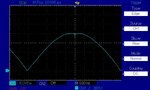
(we are designing a simple cct to blow a fuse whenever vin goes above 400V, and this is the principle involved.......or one of them....we tryed other ways but short 50us excursions above 400v couldnt be detected......the boss doesnt want much if any circuitry involved either)

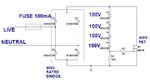
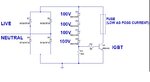
The attached is our schem of our overvoltage detector

We wonder if the "bjt detector" might be better than the fet based one...better at blowing the fuse so as to detect any >400v events?
 

Attachments

  • overvoltage detector_1.jpg
    overvoltage detector_1.jpg
    69.1 KB · Views: 148
  • bjt detector.jpg
    bjt detector.jpg
    54.6 KB · Views: 144
Last edited by a moderator:

whenever vin goes above 400V...

What happens if the Vin goes 1000V? Suddenly?

You need to have small caps and high value resistors across the diodes in the bridge. A little help for the sudden high voltages.

Also use four equal high value resistors across the zeners; the voltage should be seen equally by all the four...

Yes, you need to consider the total energy rather than the voltage; 50us at 450V may not be able to turn on the transistor fully: you see the transistor is not latching on like a regular switch...

Also consider how much energy you need to blow the fuse: perhaps it can take 100A for 1nA (just random number but you get the point...)
 
  • Like
Reactions: treez

    T

    Points: 2
    Helpful Answer Positive Rating
Hi,

I'd say it is very likely...because the isolation barrier between D and S breaks....

But I can't say this is always.
Depending on the circuit the shorted DS may cause high current. And caused by this high current (as a second failure) the bonding wire may break...then DS becomes high impedance.

Klaus
 
  • Like
Reactions: treez

    T

    Points: 2
    Helpful Answer Positive Rating
Follow c_mitra's advice about the resistors to share the Zener voltages but also be aware that the MOSFET version particularly, may not operate on short over-voltage due to the high gate to source capacitance. A normal bipolar transistor may work better.

Personally, I would quantify any spikes rather than blow fuses to prove they are there. If you really want to follow the present route, I would suggest adding a LED (with series resistors!) across the bridge output to visually indicate whether the fuse was intact or not, otherwise you have to open it to check.

Brian.
 
  • Like
Reactions: treez

    T

    Points: 2
    Helpful Answer Positive Rating
You can't say that a particular failure signature will
happen the same, for any time, voltage, current
applied to the gate. You can fail shorted at one
waveform and open at another, and before failing
D-S short maybe see other parametric issues pertaining
to gate leakage or degradation.

There are "gate zap" OTP schemes but to get the
desired (and only the desired) behavior the "programming"
I, V, t is specifically constrained.

You will want a well specified "threat map" where you
can see "must" and "must not" regions plainly, and
there had better be some daylight between the two.
Then you can better design the overvoltage detector
and the shunt switch.

If nobody provides you one, then draw what you
think you understand and get it signed off before
you spend any effort on detailed design. Otherwise
you will be at the mercy of endless what-about
and never get done.
 
  • Like
Reactions: treez

    T

    Points: 2
    Helpful Answer Positive Rating
You need to have small caps and high value resistors across the diodes in the bridge. A little help for the sudden high voltages.
Thanks, sorry i havent explained well, we are quite happy if the bridge diodes fail if there is any voltage across the bridge for any time, of >400v.
...mind you , if the bridge diodes fail immediately open then we are stuffed...because the fuse will not blow.

Regarding resistors across each zener.......we believe that no zener can ever have much greater than 100V across it.....and if any zener has a voltage much less than 100v then it will not conduct.
So we are hoping we can get away without equalisation resistors.
 

I've used that zener topology but with an SCR for a similarly high voltage crowbar.

The latching nature of the SCR seems to solve much of your problem here. Easy to find in standard fet packages for this voltage. See litelfuse.


I agree that resistors across the zeners arn't needed for the reasons you say and didn't specify any in my application. I considered caps to add a DV/DT element to the turn-on equation because I was afraid it wouldn't fire fast enough but it did. So that wasn't needed either.

- - - Updated - - -

Another even simpler alternative would be to have a lower voltage and therefore possibly smaller and easier to blow fuse simply in series with the zeners. Perhaps 100mA for example.


...I'm looking at 50mA 250V fuses for example.
 
  • Like
Reactions: treez

    T

    Points: 2
    Helpful Answer Positive Rating
I think it's useful to read IEC 61000-4-5 "surge immunity test" in parallel. Do you agree that a self destructive crowbar should at least survive a standard line-to-line 500V surge test without blown fuse?

The photo below is about "FET always go short"? Obviously not.

Bild 014.jpg
 
  • Like
Reactions: treez

    T

    Points: 2
    Helpful Answer Positive Rating
Thanks, thats a good point.
Our customer has just asked us to detect literally anything above 400V, and blow a fuse, or whatever, to indicate it.
The circuit i put up above did not work for short spikes..well, er , i mean, it kind of "ate" the spikes.....it did something weird......it literally shaved off the top bit of the mains peak (or at least that sine that came out of the AC generator...the top bit that was above 400v was shaved off, and it flat topped it to 400v plateau!) for a while, then blew.
(i am speaking of the fet based one)

Thanks FvM for the document, this looks like a really good source on transients...
**broken link removed**
 
Last edited by a moderator:

Our customer has just asked us to detect literally anything above 400V...

Unless the duration is specified, the claim above does not make sense.

Regular household AC has a period of the order of ms. Most common circuits will miss 400V 1us pulses (they will eat it up!) because of input capacitance effects.

But 10kV 1us pulses can be fatal and you need to focus on the voltage X time together. But you will need to stretch the pulse to blow the fuse.
 

The observed behavior seems expectable to me. The circuit is acting as a kind of power zener diode, energy absorbing capacity is however limited by the MOSFET safe operating area.

A SCR crowbar will always blow the fuse after being triggered, need sand filled fuse with sufficient breaking capacity at 250 VAC and surge current margin of rectifier and SCR.
 
  • Like
Reactions: treez

    T

    Points: 2
    Helpful Answer Positive Rating
Note that SCR’s will have an I2T rating which can be compared to the fuse’s rating. It should be quite easy to verify that the SCR has sufficient strength to blow the fuse.
 
  • Like
Reactions: treez

    T

    Points: 2
    Helpful Answer Positive Rating
Our customer has just asked us to detect literally anything above 400V, and blow a fuse, or whatever, to indicate it.

Sometimes it's the customer that needs the most fixing.
 
  • Like
Reactions: treez

    T

    Points: 2
    Helpful Answer Positive Rating
The FET based circuit of the first post saw the VDS of the FET becoming as the attached.
Its quite amazing, that with just a 100mA fuse, the output of the AC source was flat-topped by this circuit.
You would have thought the fuse would have blown?

I think this shows how unlike the mains these AC power sources really are.
 

Attachments

  • VDS(FET).jpg
    VDS(FET).jpg
    102.7 KB · Views: 136

You would have thought the fuse would have blown?
Surely not with this slight overvoltage. You want to record the input current to see when fuse blow comes in sight.
 
  • Like
Reactions: treez

    T

    Points: 2
    Helpful Answer Positive Rating
Thanks, i was comparing it to the real mains......as you can imagine, a circuit sitting behind a 100mA fuse would never be able to make the real mains flat-top like that.
 

Real mains distributed over long wires doesn't necessarily have super low impedance.

But what I think you're really seeing here is the slow blow nature of fuses. Even 'fast blow' fuses conduct an order of magnitude or two more current than their ratings for milli-second periods. I assume during the flat top of your waveform the fuse is conducting well more than its rating.
 
  • Like
Reactions: treez

    T

    Points: 2
    Helpful Answer Positive Rating
    V

    Points: 2
    Helpful Answer Positive Rating
Status
Not open for further replies.

Part and Inventory Search

Welcome to EDABoard.com

Sponsor

Back
Top