Continue to Site

Welcome to EDAboard.com

Welcome to our site! EDAboard.com is an international Electronics Discussion Forum focused on EDA software, circuits, schematics, books, theory, papers, asic, pld, 8051, DSP, Network, RF, Analog Design, PCB, Service Manuals... and a whole lot more! To participate you need to register. Registration is free. Click here to register now.

Flybuck design with eight isolated outputs

Status
Not open for further replies.

skn96

Junior Member level 3
Joined
May 28, 2009
Messages
26
Helped
0
Reputation
0
Reaction score
0
Trophy points
1,281
Activity points
1,667
Hi

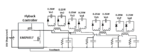
I need to design a circuit which can provide 8 isolated supply rails around 12 volt for isolated gate drives. 0.25W is max power needed for each output and so total power is 2W. Obviously a simple design solution can be two separate flybuck converter that each includes: one flybuck controller and one transformer with 4 isolated outputs. This way I can have 8 isolated outputs. However, due to the cost and size constrains I’m looking for a design with only one controller. I have also small dual output coupled inductors available. Design solution shown in below uses coupled inductors . In this picture as shown only one controller is used and four output LCR are effectively in parallel. Since only one feedback is available the output voltage of the first LCR filter is sensed and fed back to the controller. However, since the loads of all four LCR and secondary outputs are identical we can assume the feedback system help also to regulate the other three primary outputs.

Now I'm wondering if this solution will work for me or not? Do I have to have a feedback at all, considering the fact that the input is fixed regulated 15 volts? Maybe this system can work open loop? If there is any alternative solutions please let me know.

Thanks.
 

Attachments

  • flybuckDesign.PNG
    flybuckDesign.PNG
    20.5 KB · Views: 134

The circuit as shown is very bizarre and definitely won't work as intended. The feedback scheme won't properly control your outputs at all.

You should use a flyback or pushpull converter with an appropriate driver/controller (not a synchronous buck converter). If your input supply is indeed well regulated, then you might opt to not use any feedback for the isolated supplies (at most, just take feedback from one supply and assume the others are all cross-regulated). However you should rigorously test a system without feedback to make sure nothing nasty happens during transients (especially power up).

There are numerous chips and transformers specifically designed for making gate driver supplies:
https://www.digikey.com/en/product-...grated/transformer-drivers-for-isolated-power
https://www.ti.com/isolation/transformer-driver/products.html
https://www.linear.com/product/LT3999

Thanks for your reply. This topology I posted is flybuck which has been introduced by TI and is very helpful for very power isolated power(<5W). Here you can see an application note addressing this:
**broken link removed**
Flyback and push pull are more expensive than this topology and they better suit higher power applications(>5W).
For my application I need at least 24 isolated low power outputs. That means I need to use 3 of the shown circuits (3*8=24). Using flyback or push pull are going to be more expensive.
Would you please advice why you think the shown topology is not going to work for me?
 

Ok I see, it's one of TI's bizarre topologies... basically a flyback with a clamp on the primary. Yeah it should be okay for generating any number of outputs, so long as the components and loads are fairly well matched.

The one advantage this has is that it provides a very simple method of roughly regulating the isolated outputs from the primary side. Other than that I don't see any cost or performance advantage over a flyback or push-pull. In any case the cost will likely be dominated by the transformers/coupled inductors.
 

You can use 1 controller for the multiple output Flyback converter also. In flyback you can make the regulator regulate the combination of outputs or more precisely, weighting the outputs. For some reason you want to use 8 outputs in the Isolated Buck but no 8 outputs in the Flyback.

The Isolated Buck uses 2 switches and one is high side switch and hence high side driving circuitry.
The primary side regulation will regulate that... the primary side.

- - - Updated - - -

You can also make an isolated boost which uses 2 switches, but why? when we have an isolated buck-boost with 1 low side switch...
 

Status
Not open for further replies.

Similar threads

Part and Inventory Search

Welcome to EDABoard.com

Sponsor

Back
Top