Continue to Site

Welcome to EDAboard.com

Welcome to our site! EDAboard.com is an international Electronics Discussion Forum focused on EDA software, circuits, schematics, books, theory, papers, asic, pld, 8051, DSP, Network, RF, Analog Design, PCB, Service Manuals... and a whole lot more! To participate you need to register. Registration is free. Click here to register now.

Help needed to repair a Sony Trinitron KV-2165MT power failure

Status
Not open for further replies.
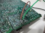
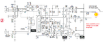
You may have an open-circuit R609, which will remove the ground reference from pin 2. This resistor senses peak current through the STR and could have gone open due to the fault.

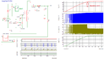
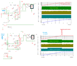
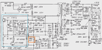
Below is an internal diagram of the STR chip to help understand the working. R609 (R805) can be seen to be in series of the main switching transistor.

When the peak emitter current is too high, the voltage drop over R805 will turn on VT3's base-emitter junction, which will turn on VT2, that will shunt current away from the base of VT1, turning it off.

The opto feedback performs the same function. When the 112/5 V line goes too high, opto turns on, turning on the external PNP (Q801), which also turns on VT2.
 

Attachments

  • str.png
    str.png
    109.6 KB · Views: 300

Unfortunately, R609 is still intact!

By the way, what is the source for the 115V in this board? As far as I can see, it's T601. So, why the cathodes of D604/D608 read 81.7V ?
 

Let's think about this:

You measured the voltage on C604.
The reading across C604 pins was around 320 VDC

You said that you measured a low resistance between pin 1 of the STR and C604 positive.
Resistance between Pin#1 of STR and C604 is 0.1Ω
Then you said that you didn't measure any voltage between pin 1/2 of the STR.
Pins 1/2 of STR: 0 VDC
If we follow pin 2 back through R609, it goes to the negative rail which is connected to C604 as well.
Unfortunately, R609 is still intact!
Should be 0.15 Ω

So, something is not making sense :thinker:. How can you measure 320 VDC on C604, but get no voltage on pin 1 of the STR? You already stated that there is a very low resistance between pin 1 and C604. You may have a broken pcb track between R609 and DC GND which will cause these strange readings. Inspect the tracks for GND continuity to R609.
You should carefully do the measurements again. Perhaps you referenced the meter probes between the wrong points when taking voltage measurements. I would suggest keeping the negative probe of your meter fixed on the GND side of C604 and remeasure on positive of C604 as well as pin 1 of STR.
 

Yes, you were correct, it's a bit confusing. In fact, because of the dozens of tests I've done switching to different GND points, different AC/DC modes, I got almost lost in the dark.

But what I'm pretty sure about is that I didn't read any voltage across Pins 1/2 of the STR.

Yes, I believe it was around 0.15Ω.

I won't be surprised if the board has a broken trace as I have already found a lot of dry and cracked solder joints across the entire board.

I will do the tests as you suggested, and I will try to trace the GND back through the R609 and will let you know as soon as I can.

Thank you for your help!

- - - Updated - - -

Now, I have an update regarding the older set, the KV-2162M9, which was working lately. I have replaced the 400V/220uF caps, as well as, the 160V/330uF. The clicking sound has gone now, but the set still refuses to start up. When turning power on, the set makes a loud noise just like if it's starting up normally, screen shows tiny flashes on certain corners for a bit of a second, then the power LED goes off. When turning off, it makes that crackling noise as well, which might be indicating the PSU is working well?
 

Hello guys,

I'm back with some interesting results so I really appreciate your further assistance.

As e-design said, it didn't make sense that I got no voltage across Pins 1/2 of the STR while the reading was 320 VDC across C604 pins. Pins 1/2 of the STR are connected directly to those of C604, so it's really weird that I didn't get any voltage there. I decided that I should spend more time investigating that area and below are the results I have obtained.

First of all, continuity test between STR Pins 1/2 and C604 checks, so probably I don't have a broken trace in between. Second, I have taken the following measurements with the negative probe of my DMM fixed on the negative pin of C604:

1- STR Pin 2: 318 VDC
2- Q603: All pins read 318 VDC
3- Q601: Same as Q603, with the exception of making some fast oscillation/hissing noise out of some other component, probably a cap or the transformer or the STR itself, when touching the base with the probe.
4- Pins 4/5 of IC603 read 318 VDC.

When fixing the positive probe on the positive pin of C604 instead and taking measurements with the negative one, the results are totally different. Pin 1 of STR reads OL, no voltage whatsoever. Again, reading Pins 1/2 of the STR directly results of OL, too. The funny things is, I can read the voltage across the cap (C604) in different polarities (318 VDC or -318 VDC) but it's not the case on Pins 1/2 of the STR, where the reading is always OL. Pretty weird, isn't it??

Now, the serious fun started when I switched to my analog multimeter. What follow are the results I've got:

1- Negative probe of the analog meter is fixed on the negative rail of the bridge rectifier/C604. The meter is set on 1000 VDC, 250 VDC would be out of range as we are measuring a potential of more than 300 VDC. When measuring Pin 1 of STR, the meter reads 110 VDC (again, the scale is 1000 VDC). All other pins read 0 or OL, but pins 8 and 9 pull the needle back (negative reading).

2- Q603 gives around -1.5 VDC on all of its pins.

3- PS801 (the 115V line) turns out to be 60 VDC when measured with the analog meter (reference is cold GND).

4- No output whatsoever on any pin of the secondary side of T601, except 1 VDC on Pin 12. (reference is still cold GND).

5- Back to STR again, the reading I got with the analog meter was really strange, considering the earlier results. Pins 1/2 now read a voltage close to that of C604, but it was higher by almost 30 VDC. On a scale of 1000 VDC, the reading was 110 VDC across Pins 1/2 of STR, while it was around 85 VDC across C604, which is supposed to be the source for that voltage on the STR.

Finally, when getting back to the DMM, using the cold GND, I got the following measurements, which are somewhat corresponding to those on the schematic:

1- STR Pins 2 ~ 9: - 57 VDC
2- IC603 >>> Pin1: 14.75 VDC, Pin2: 14 VDC.
3- Q603: -58 VDC on all pins

Thank you again for your help!
 

1- STR Pin 2: 318 VDC
Are you sure? Measured between negative C604 and pin 2?
Can't see how this can be possible as pin 2 goes back to negative via R609 (0.15 Ω) and should be near 0 V
If this was true, then R609 would have blown open long ago. That will happen if the internal switch in the STR goes short collector-emitter.

Please keep your one probe on C604 neg and measure STR pins 1-9.

When you measure the 115 V then your -probe should be on GND side C609
 

Hello e-music,
I deeply apologize for the long absence.
My wife's PC decided to pack it in, and she had important work to complete, so she had to
sponge my computer until she was done.
I have to admit that I require some time to answer any posts, as I like to think of as many
alternatives as possible before uttering a word. :smile:

OK, first up, I need to know exactly what component/s have been replaced in this set. We'll
get to the other telly later.

When ever you do any static measurements, to be 100% on a component, you need to either
lift one leg out of circuit or in the case of capacitors, remove them entirely. This is to ensure
that no other components in circuit will affect any of your readings.
SMD is the same, you need to remove the part entirely, as unfortunately you can't lift a leg.

E-design is correct.

How can you measure 320 VDC on C604, but get no voltage on pin 1 of the STR?

It definitely makes no sense.
Due to the PSU not oscillating you should be getting an identical voltage on Pin 1 of IC601, as its
only passing through a virtual short circuit via the chopper transformer. But when it is oscillating,
the 81.7 volts shown in the schematic would be correct, and not be at the same potential as C604.

I need you to measure R615. But make sure you lift one leg out of circuit, then get your reading.
This component should be the start-up resistor for IC601.

If you have a look at the picture below, it will show you the drive needed for Q3 of the internal
diagram:

Om2ZQG4.jpg


If you find that R615 is OK, then we need to check the 3 diodes in the PSU for leakage.
Once again, lift one leg on each of the diodes (D602, D603 and D607).
Set you multi-meter to diode test and measure them both ways. One way (Positive probe to anode
and negative probe to cathode [Forward-Biasing]) you should get a reading. Something like .607
or there-about's.
You should get an open circuit reading the other way around [Reverse-biasing].

If you find the readings correct, we need to do what they call, "a punch-through" test on them.
Set your multi-meter to the highest ohms setting it has, then measure each diode reverse-biased.
If you get any reading at all, then there's a good chance the diode/s are leaking.
No point doing a forward-bias test, as the readings won't mean anything on high ohms.
If you need to replace D603 and/or D607, you can replace either with an 1N4148. They are as common
as muck.
You can replace D602 with an FR504, BYT52G or BYV13. Not as common, but source-able.

If all is well, we now need to start measuring resistors, that have either gone high in value or open
circuit.
Do an in-circuit static ohms measurement on each one first, and if you're getting obscure readings on
your meter, you'll have to lift one leg of the component out of circuit. And in the case of SMD resistors,
you'll have to remove them entirely, sorry to say that. :sad:
Concentrate on the easiest to remove or lift a leg/s up first.

If all good, then you're going to need to remove Q601 and Q603 and do a forward and reverse bias test
on both of them.
I have to say at this point, it isn't easy to remove a three legged surface-mounted device using just a
soldering iron, but here's a fairly easy way of doing it:
Place a blob of melted solder onto each pin of the transistor.
Now alternating between the three elements with your iron as quick as you can, allow each ones solder to
melt to the point that the transistor starts to move, then just slide it to one side away from other components
and/or joints and let it cool.
Lastly on this point, try not to heat the transistor for too long, as this may damage it.
If you're finding it difficult at first, then allow it to cool, then try again. Keep repeating this, so you don't
damage the bugger.
You may encounter one problem, and that's if the transistor itself has been glued down at the factory. If so,
it won't be easy to remove.
The only way I know of how to do it with just a soldering iron, is to place a blob of solder onto the Collector of
the device, leaving the iron in place, get a small thin sturdy piece of metal and try levering it up until one side
lifts from the board. It may take a bit of pressure, as that glue is super strong. :sad:
What ever you do, make sure your iron is constantly on the Collector. I Doubt you'll be able to melt or soften the
glue though.

OK, follow the next procedure when replacing or refitting the transistor:
Using de-soldering braid, remove all the solder off each pad.
Next, place a small blob of solder onto say the Base of the pad, then, with a set of tweezers, place the transistor
onto the pads and heat the blob so the base pin moves into its proper place, at the same time, ensuring the
Collector and Emitter pins are lined up as well. Make sure its laying flat as as possible.
Once you're happy with its placement, solder the other pins, making sure all of the pads are wetted, but don't
over-do it.

OK, once the transistor/s are out here's a hint on measuring them:
See the picture below for the pin configurations:

aAqCG3o.jpg


Lets say you're going to measure Q601 (2SA1162), which is a PNP device.
Set your meter to diode test.
(1) - Place your negative probe onto the Base of the transistor and the positive probe on the emitter.
You should get a reading of around .700 or something near that.
(2) - Leaving the negative probe on the base, place the positive probe onto the Collector. You should
again, get a reading similar to above.
(3) - Now place your positive probe onto the Base and the negative probe on the Emitter. You should
get an open circuit reading. Same reading when you place the negative probe onto the Collector.
(4) - Next, place one probe (it doesn't matter which one), on the Collector, and the other on the Emitter.
You should see an open circuit reading.
(5) - Swap the probes, and once again, it should be open circuit.

Now we need to do a punch-through test on the transistor. You pretty much repeat the above process,
but there is no need to do Steps (1) and (2). They will be meaningless.
Set you meter for its highest ohms range and proceed to do the punch-through.

The same exact method will apply to measuring Q603 (2SC2712) NPN, except that your readings in step
(1) and (2) will show that they will be open circuit.
Its not until you do Step (3), that it should show a reading. It should be similar to the PNP test, around
.700 or so.

If you need to replace either or both transistors, these are recommended:
2SA1162 ---> BC856A
2SC2712 ---> BC846A

The .700 readings, or the .607 reading on diodes just tells you how much voltage is required to bias the
device. Therefore a .700 reading will indicate a 700mV forward conduction potential required.
ALL readings I've indicated are just approximates and can vary quite a bit between devices.
i.e. Schottky diodes usually have lower conduction requirements than standard diodes. Zener diodes
should be higher than standard diodes.
Same goes for transistors, though they are pretty much on par with each other.

The above tests will allow you to determine if an unknown transistor is either NPN or PNP.
By having the positive probe on the Base and getting readings on two of the other elements will tell you
its an NPN. Positive probe to the P of the device.
The reverse is true for PNP transistors.
The above won't determine what pins are what, but at least it will determine its polarity, as well as identifying
the base pin.
So, when ever doing the above and you get two readings, then just look at what color probe is on the one
pin that stayed where it was. That will give you its type, as well as the Base pin.

As for FET's and MOSFET's, it is not possible to do static test as shown above. Here you would need a
component analyzer to get any accurate readings. The best you can do is to determine if the component
has gone short circuit.
But when doing a short circuit test with the part, you need to first make sure you have no static in your
body, then just place a wet finger across the three legs and then do your measurements.
The reason for doing the wet finger test is to discharge any internal capacitance charge that may be present.
Many a time I've measured brand new devices and in some cases they showed me that they were partially or
completely shorted. This is where a wet finger helps.

One last thing on transistors, they are NOT all made the same.
Some have internal resistors which make it difficult to conduct a fairly conclusive test.
Other transistors actually have two transistors in one, connected in parallel. These are high gain types and
are usually called Darlingtons.
There are many with internal diodes, mainly across the Collector/Emitter junctions, which are mainly seen
in Horizontal Output transistors. The internal diode is required to dampen the collapsing magnetic field of a
flyback transformer. Without it, the transistor would blow in micro-seconds.
In the early days, they used a separate dampening diode, but due to technology improvements, they were able
to integrate it within the device itself.

Lastly, there is NO guarantee that doing the above measurements is totally foolproof. I have been caught out
in the past, where I thought the device was good, yet when I replaced it, the set worked.
Once we had such a device and we put it through a bevy of tests such as, its gain (βeta), set it up in a biasing
circuit and it worked well and we also did curve tracing on it with its parameters being very close to what the
datasheet info gave us.
No reason for it to be faulty, but there you go. :bang:
The only conclusion we could come to was the fact it didn't like high voltages. This transistor we tested was the
blue cathode output transistor on the CRT board of a Sharp TV. Unfortunately when we bias tested it, we used low voltages
only. Those output transistors require 150 plus volts for proper operation.

So, my advise to anyone doing repairs, if in doubt, replace it. Provided you've done as much testing as possible.
Otherwise it will only confirm that that's one component you know works.

Please let me know how you get on, and sorry once again for the lengthy post.
Regards,
Relayer

P.S. @e-music I'll try to answer you queries about the other set tomorrow. Sorry, but I've spent too much time on this post and
I need to do stuff. :smile:
 
Last edited:
Are you sure? Measured between negative C604 and pin 2?
Yes, I'm pretty sure. I measured it dozens of times and just switched the power off now after re-soldering every solder joint at the PSU and almost 90% of others across the lower part of the board around the PSU, still the same result. If you want, I can take some photos and show you the results.

When you measure the 115 V then your -probe should be on GND side C609
Yes, that's what I did.

Thanks

- - - Updated - - -

Hello Relayer,

Thank you very much for your comprehensive diagnosis reply. I really appreciate the time you've taken to cover all these details and please take your time in getting back here. Of course, priority has to be for your own stuff, no worries there! :)

I do need some time myself to get back to the set and do the tests and report the results back.

Thank you again, and talk soon! :thumbsup:
 

Here is a very simplified version of a typical power supply like yours. The transistors Q1/2/3 and diode D2 is all in the STR power chip. The circuit needs the start-up current through R4 (R602/17 in your case). Once switching action starts, the feedback winding keeps it going. Output voltage will increase until the voltage feedback loop kicks in. When that happens, Q3 will start to shunt current away from the base. This will decrease the on-time of the main transistor, as can be seen in the collector current, which will prevent the 115 V from increasing any further.

The diagram uses a common GND for simulation purpose only.

Make sure R602/17 are the correct values.
 

Attachments

  • TV_PSU.png
    TV_PSU.png
    70.6 KB · Views: 143
Hello Relayer,

I just managed to get to the set and do all the tests following your instructions literally, but before we get to that, I'd like to show you something regarding the aforementioned reading for Pins 1/2 of the STR.

In order to make sure I didn't get an incorrect reading because of a loose contact, residue on the tips of the probes, etc, I have soldered cables to the Pins 1/2 of the STR and now I have a rock solid contact between those pins and my multimeters.

IMG_1728.jpg

As you can see in the following photo, the set is live now and the DMM reads "OL".
Live_Set.JPG

Anything more stranger than that? Makes sense now?

The following shows the same thing repeated with the analog multimeter. Now, the reading is something around 200V (110 VDC on a scale of 1000 VDC).

Analog.JPG

When switching the power off, the DMM shows a reading only when the voltage falls to around 6 VDC, as you can see in the following photo taken 4~6 sec after switching power off

Switched_Off.JPG

Will send the last test results in a subsequent post or update this one.

- - - Updated - - -

Components changed so far:
- IC601, IC602, IC603, Q601, Q602
- Q802 (H.OUT): This has been changed the first time I opened the set, as it was shorted out completely.

- R615 checks, 680k Ω (out of circuit)
- D602, D603, and D607 pass all the diode tests and I've done a "punch-through" test on all of them, and they all seem to be ok.

Last thing I have replaced is Q601 but didn't test the set or take measurements after that. I'm thinking about replacing the PS801 with a thin wire and test the set again and see if there's any difference.

I'm really not sure whether there's something else to look at next, sure there has to be, but in my situation, I'm almost giving up. Just need someone to explain why the DMM was reading "OL" when the set was on? I thought there's smoething I didn't understand as I'm not very acquainted with analog circuits.

Thank you again for all of you who participated in this thread! Your help and efforts and much appreciated!


e-music

- - - Updated - - -

I have soldered a jumper-wire in place of the PS801 and tested the set. After 18 seconds of turning on, I get a horizontal line in the middle of the screen. I took this footage:

https://drive.google.com/open?id=1_OHarF_BYLg1T62P4-PH5jW-0kV0rbjG


I believe this is also common when the PSU is faulty, so it's not necessarily the V.OUT (IC551).

Let me know what do you think.

- - - Updated - - -

The 115V line measures 52 VDC now. All STR pins measure -57 (with cold GND).
Pin 6 of IC551 (V.OUT) measures 11.9 VDC.
 

Attachments

  • IMG_1728.jpg
    IMG_1728.jpg
    504.2 KB · Views: 179

At least, the PSU is giving some power as the horizontal stage tries to start up. So the PSU is running at low power. Maybe trying to start and something is throttling it.

BTW. The OL reading means Over-Load as the digital meter sees some switching pulses on pin 1 and can't auto-range fast enough.

Make sure R602/17 are the correct values.
What did they measure?
 

Hello E-design,

Yes, you are correct. But as far as I remember, I got the same result without auto-ranging. If these pins are virtually duplicates of C604 pins, then why I'm getting the correct reading while measuring across C604 pins?

I didn't measure R602/17 yet, and thank you very much for reminding me again. I will measure them and let you know asap!

Regards

- - - Updated - - -

I just got the readings.

R602 measures: 98k Ω.
R617 measures: 46.1k Ω.
 

Yes, you are correct. But as far as I remember, I got the same result without auto-ranging. If these pins are virtually duplicates of C604 pins, then why I'm getting the correct reading while measuring across C604 pins?

If there is any switching action, there will be short spikes on pin 1 with amplitude much higher than the voltage over C604. The analog meter only sees the average value and can't respond to the peak pulses.

It appears that the PSU sees some condition that put it into a protective mode. It may not necessarily be due to an overload, but a faulty part may cause it to think there is an overload. I think we should take a closer look at the components around the feedback winding. If it isn't getting enough drive, it may limit the power that the PSU can deliver.

You can also check C606 for any leakage. This often happens with these high-voltage caps over time. This will put a strain on the PSU and put it in a current limit mode.

Is there any way you can measure the voltage over C619? This will give us some idea of any feedback drive. If you have not checked C619, then do so. If you have not checked R604/23, C607/26 then check and replace if necessary. Often it is impossible to check these small HV caps without a proper tester under rated voltage, and just easier to eliminate them as suspects by replacing them with a new correctly rated part.
 

Below I expanded on my previous example to show how base drive will affect the available power of the PSU.

In the top diagram, we increase the load on the PSU by lowering R3. As the power is limited, no voltage regulation point is reached by 40mS.

The next diagram, we switch in an additional voltage source (proportional of the voltage over C619 in your case) through R9, which drives a bit more current into the base. This happens at the 28mS mark. As it can be seen the power in TX1 steps up and the collector current increase. The voltage regulation point is reached sooner at around 35mS. Once the regulation point is reached, collector currents drops back to normal.

So it should be obvious if something prevents the transistor from getting the proper base drive control, power will be severely limited, and output voltage will stay low.
 

Attachments

  • power_control.png
    power_control.png
    124.3 KB · Views: 133

Hello e-music,
This will only be a brief post, as I have quite a bit on today...

Firstly, follow E-design's suggestions, as they are very sound.

When you measured the 52 volts on the 115 volt rail, was that with the dummy load attached
and PS801 removed from circuit? Or did you measure after you inserted the wire link?

I believe this is also common when the PSU is faulty, so it's not necessarily the V.OUT (IC551)

You are essentially correct, but due to the horizontal line being short and doesn't cover the entire width of the
screen, its more than likely due to the reduced main rail voltage. That's why, if the set was actually working
you would get a shrunken picture on all sides.
The vertical collapse would definitely be due to the reduced voltage coming out of the flyback transformer that
supplies the 26 volt rail to the vertical output IC551.

There is also a possibility that the protection circuit in the horizontal stage is kicking in, thus reducing the output
of the PSU deliberately.
If the above is true, then you need to disable it to see what will happen to the voltages around the circuit.
Here's where the risk factor comes into it. By disabling the protection circuit, it may cause an overload and take
out the horizontal output transistor and perhaps other components as well, as the telly will no longer be protected.
But at the same time, it may fire up with no destruction and will allow you to diagnose the actual fault much better.
I'll leave it up to you as to whether you want to take the risk in the protection circuitry being disabled.

If you do decide to disable the over-current protection, you need to lift one leg of R562 (2.7kΩ), located roughly on
the bottom left side of the horizontal output transformer (T851), next door to D561.

But before proceeding with disabling the protection, I need you to measure Pin 22 of IC301. This is the output trigger
for the protection circuitry.
It should measure 1 volt. Anything higher will mean protection is being triggered.
If you get zero volts on it, or its above 1 volt, then you need to disable the protection. But what ever reading you do get,
we still need to disable the protection to at least eliminate that as the cause of the low main rail voltage.

The above could all be just a furphy, as protection circuits usually disable the horizontal stage altogether and shouldn't
effect the 115V rail. But stranger things have happened, as the fault may lie in the protection circuitry itself. Its not the
first time I've come across this.

Please let us know how you get on.
Regards,
Relayer

EDIT: Before disabling the protection circuit, make sure you replace that wire link with the original fuse, as this should
minimize any damage, if any, to other parts of the set.
 

Obviously, the added base drive must only be supplied at the proper time when the transistor needs it. Below I have added the drive feedback and plotted the collector current versus V-drive.

- - - Updated - - -

Relayer, I feel he should first get the PSU fully functional and tested with a lamp load for correct output voltage. Once the power supply is healthy then he can look for other faults. The working PSU should self-limit and protect itself for most overloads when connected back onto the 115 V rail. At this stage, we are chasing our own tails and don't know if the PSU, HS, VS or a combination is causing the throttling.

I would like to clear the PSU as a suspect first. If the PSU can't deliver enough power at the correct output voltage then there is no point to test other circuits. If he had a separate power supply that could go up to 115 V and with enough current and limit control, then the set could be tested this way.

e-music, do you have a scope?
 

Attachments

  • power_control1.png
    power_control1.png
    45.4 KB · Views: 136
  • PSU_test.png
    PSU_test.png
    125.1 KB · Views: 144

Hello E-design,

Relayer, I feel he should first get the PSU fully functional and tested with a lamp load for correct output voltage. Once the power supply is healthy then he can look for other faults. The working PSU should self-limit and protect itself for most overloads when connected back onto the 115 V rail. At this stage, we are chasing our own tails and don't know if the PSU, HS, VS or a combination is causing the throttling.

I have to agree 100%. I have to admit that my theory on switch-mode designed PSU's are fairly limited.
Plus its been almost 20 years since I've done any serious repair work in the trade.
By the way, I was wrong in regards to the start-up resistor as being R615. You were spot on with it being
R602 and R617. Sorry about that. :oops:

@ e-music,
As E-design has recommended in the above quote, please hold off on my suggestions in my last post.
He is totally correct in getting the PSU running first, then we can worry about the other stages if the
telly still stubbornly refuses to work properly when the power supply has been bought back to full life.

Please follow E-design's steps as set out in his last few posts.

I've checked all the posts and there's been no suggestion, therefore can you please check R603 (68Ω 3W).
Of course with one leg out of circuit. :wink:

Lets hope we can get to the bottom of this and get it sorted. Please don't give up, as I feel we are not far
off in nutting this thing out. :cool:
Regards,
Relayer
 

Is there any way you can measure the voltage over C619? This will give us some idea of any feedback drive. If you have not checked C619, then do so. If you have not checked R604/23, C607/26 then check and replace if necessary. Often it is impossible to check these small HV caps without a proper tester under rated voltage, and just easier to eliminate them as suspects by replacing them with a new correctly rated part.

Thank you again for your continuous follow up to this post, and I really appreciate the info and the snapshots attached. They are very helpful to understand how this PSU starts up.

Of course, I will get to the set as soon as possible and take the measurements for C619, as well as, all the others as suggested and get back with results once done. I don't have an ESR meter, but my DMM has a capacitor test mode. It's not tha reliable, but it works sometimes.

- - - Updated - - -

@ Relayer:

Hello again,

I'm just fine with brief post, don't worry about it!

Yes, I agree with you that e-design's guidelines seem very sound and I will make sure to follow them first before attempting to do anything else.

When you measured the 52 volts on the 115 volt rail, was that with the dummy load attached
and PS801 removed from circuit? Or did you measure after you inserted the wire link?

Actually, the light bulb was removed since I did that test and never connected it back again. I just soldered a wire jumper for PS801 and measured the voltage on the line with the next stage being the load.

but due to the horizontal line being short and doesn't cover the entire width of the
screen, its more than likely due to the reduced main rail voltage.

Yes, I agree with you. I have made a research and found out that the common symptom for the V.OUT fault is a full width horizontal line, at least for the majority of people reported similar problem with the V.OUT stage. On the other hand, it's obvious the PSU sees something that forces it to switch to stand-by or protection mode, because the red led turns off after 3 seconds from starting up. So, the voltages I'm getting across the board are not the correct one since the PSU wasn't working normally.

Thank you again for your follow up!

- - - Updated - - -

@ Relayer,
As E-design has recommended in the above quote, please hold off on my suggestions in my last post.
He is totally correct in getting the PSU running first, then we can worry about the other stages if the
telly still stubbornly refuses to work properly when the power supply has been bought back to full life.

Please follow E-design's steps as set out in his last few posts.

I've checked all the posts and there's been no suggestion, therefore can you please check R603 (68Ω 3W).
Of course with one leg out of circuit.

Lets hope we can get to the bottom of this and get it sorted. Please don't give up, as I feel we are not far
off in nutting this thing out.
Regards,
Relayer

No problem Relayer, and thank you again for your help. I will check R603 and let you know. Yes, you were correct in not giving up now, since we already spent a lot of time and effort on this already, replaced a bunch of components so far, mainly the most critical ones for the PSU. I feel we're pretty close, too, and with your great help and guidance, I'm sure we can do it together.

Thank you again and best regards,


e-music
 

On the other hand, it's obvious the PSU sees something that forces it to switch to stand-by or protection mode, because the red led turns off after 3 seconds from starting up

We don't know if the PSU itself is healthy at this stage, so we must be able to verify that it can operate into the lamp load (you may need to parallel some lamps to get to about 40-60 W, but start with one first) at set voltage. Once we have a full working PSU, we can troubleshoot other problems.
 

you may need to parallel some lamps to get to about 40-60 W, but start with one first

Perhaps I forgot to mention that the one I have here is a 60W lamp. Do you think it's enough to bring the PSU to the full working voltage, or you suggest adding another 20~40W lamp in parallel with the first one?

Thanks
 

Status
Not open for further replies.

Similar threads

Part and Inventory Search

Welcome to EDABoard.com

Sponsor

Back
Top